
Journal of Numerical Analysis and Applied Mathematics, Vol. 1, No. 2, November 2016 Publish Date: Nov. 21, 2016 Pages: 39-59
Mathematical Exact 3D Integral Equation Determination for Radiotherapy Wedge Filter Convolution Factor with Algorithms and Numerical Simulations
Francisco Casesnoves*
IEEE (Institute of Electrical and Electronics Engineers, Individual Researcher Affiliation), Tallinn, Estonia
Abstract
Analytical and numerical Gaussian models have been used in recent decades for radiotherapy treatment planning software/calculations, to perform accurately radiation dose delivery –numerical, analytical, or numerical-analytical. The objective of this contribution was to obtain an exact dose delivery, 3D analytical-integral-equation solution, for the triple Gaussian model of wedge filters, since previous/initial 2D approximations of other authors, although correct, were not completely exact. The generic triple Gaussian model of Ulmer and Harder sets an Attenuation Exponential Factor, AEF, well approximated in 2 variables, namely, u and z. This specific contribution of the research contribution was specially focused on numerical methods and approximation analysis of the integral equation resolution –with extent details about numerical data, Appendix 3. In this paper we set a detailed spatial-spherical geometry discussion/proof towards the determination of a 3D integral form of the delivery dose in water. In other words, with an AEF for magnitude-values of variables u, v, and z. Simulations, based on these new determinations were shown with sharp presentation of the numerical-computational software and functional programming series development. Computing encode techniques are explained with some practical examples for numerical radiotherapy calculus.
Keywords
Radiation Dose, Attenuation Exponential Factor (AEF), Simulations, Nonlinear Optimization, Matrix Algebra,
Spherical-Spatial Analytical Geometry, Trigonometry, Series Approximations
Received: August 3, 2016
Accepted: September 18, 2016
Published online: November 21, 2016
@ 2016 The Authors. Published by American Institute of Science. This Open Access article is under the CC BY license. http://creativecommons.org/licenses/by/4.0/
Contents
1. Introduction 2. Determination of AEF 2D Demonstration with Further Precision Development 3. Mathematical-Geometrical Method 4. Integral Resolution and Further Mathematical Development 5. Computational Simulations and Graphics 6. Computational Programming with Comparative Implementation of Algorithms and Formulas 7. Software-Programming Development with Specific Algorithm Differentiation 8. Discussion and Conclusions 9. Scientific Ethics Standards and Acknowledgements Appendix 1 Appendix 2 Appendix 3
1. Introduction
Wedge filters (WF) constitute a common radiation-dose-distribution device used in Radiation Therapy, Inverse/Forward Treatment Planning Optimization (TPO), to conform tumor shape during radiation delivery. They belong to the generic group of Beam Modification Devices (BMD) [1, 3, 4]. A Beam Modification Device (BMD) is defined as follows,
any physical-engineered device that modifies the emerging radiation IMRT/IMPT/photon-beam beamlets in one or several of their physical-geometrical parameters, whose consequence is a better optimized/precise radiation delivery
The WF function is to attenuate the radiation beam in increasing magnitude, usually along the transversal direction to the photon-beam. In Table 1, it is put forward a geometrical-concept brief of some important BMDs, [3, 4, 56], and their principal functions, mathematical conditions, and physical dosimetry consequences in dose quantification.
BMDs are in constant evolution, not only in new inventions1, but also in the optimization methods to approach the maximum radiation delivery possibilities of each one [11-13].
Table 1. BMDs basic geometrical concepts and details.
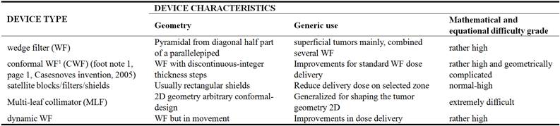
Following Table 1, the MLC constitutes the state-of-the-art in 2D shape modification of beams, and satellite blocks and filters, [11-13], could have several geometries. They keep the edges centered at LINAC radiation focus, usually –so-called monoconcentric satellites. When using any BMD of Table 1 or any other variety, the IMRT or pencil-beams distribution(s) can be reshapened ‘a la carte’, or according to some pre-designed standard modifications for specific tumors, geometries, isocentre location, and anatomical coordinates [11-13, 55, 56]. This technique, using previous accurate data, and got by simulations or experimental, saves planning time and running calculations/time in the planning system. The concept of spatial modification differences between the MLF and the WFs is also important. WFs modify the beam/beamlet in 3D, that is, coordinates X (WF surface), Y (WF surface), and Z (depth direction towards the isocentre). In a WF, it is straightforward guessed that Z variable is also modified since X and Y beam-parameters at any interior level of the wedge depend also of the Z value. Therefore, MLC modification is in 2D, and WF one is in 3D. Each one has different functions and utilities, MLC is usually set for tumor complete shape fitting, and WFs are more related to dose distribution along different levels of the tumor volume, namely, PTV, planning target volume.
Therefore, BMDs usage can be justified for a sharp rationale in dose optimization at PTV, and at OARs precise dosimetry reduction. That is, fundamental reduction of dose at organs at risk (OARs), specially critical radiosensitive organs, and also non-critical. That is because those tissues could play a role in further protection of side effects of chemotherapy and/or inmunotherapy adjuvant to radiation. BMDs contribute essentially to dose delivery optimization, and LINAC/IMPT optimal functionality. They set also precision on the anatomically pre-designed geometrical constraints of the tumor, e.g., MRI, NMR, or Computerized Axial Tomographies. In this way, BMDs prepare accurately the tumor and OARs zones for optimal chemotherapy/immunotherapy treatment [7-13, 18]. By plain language, maintaining narrowly normal physiological conditions for chemo/immunotherapy best results. Strictly speaking, in immunotherapy any lynphatic physiological structure that is related to the natural immunological system should be considered an OAR, because the new-advanced inmuno-drugs keep an essential role linked to the lynphatic physiology [Fig. 1] –lynphatic nodes mainly, and ducts and vessels also, for instance in neck-localized tumors. According to the recent oncology advances data, both in chemotherapy/immunotherapy and modern statistics, related to progress in rate of complete cure of tumors and chronical survival time of cancer disease, it is possible to assert, cautiously, a pre-hypothesis criterion. In future, radiation therapy, IMRT or photon-beam, proton therapy and related radiation techniques, such as electron therapy, will be clinically used, in no few cases, for an initial tumoral tissue destruction [39]. That is, to prepare the field for the physiological-related tools that will convert cancer in a chronic disease definitely in a not very far future. In other words, radiotherapy will change its clinical applications in oncology towards an essential-secondary complementary technique to accelerate the cancer treatment, and maximize the first complete elimination of the gross tumor volume –the inaccessible tumoral complete tissue, or the rest of tumor after surgery when it is anatomically accessible and/or encapsulated [39]. Just to remark also, that oncological surgery, especially in cases when tumors are accessible and encapsulated, constitute a clinical technique with similar/essential efficacy level for this primary stage to reduce, at least, the tumor to its minimum size. Therefore, in general, BMDs are used for superficial tumors [30], such as breast, prostate, some brain tumors, and others [ref]. Expressily, dose delivery control and modification is better achieved at low-depth radiation distances proper of superficial tumors. The reason is that those physical laws that create emerging beam magnitudes correction factors, have a lower influence in the modification of the desired parameters of the original emerging beams or IMRT/pencil-beams beamlets –for example, the simple inverse square law, or the extensive and varied tissue in homogeneities factors [11-13, 30]. Modern advances both in conformal radiotherapy, immunotherapy [3, 2, 35], specific RT conditions for methastasis cancer, and adjuvant oncological treatment with chemo-inmuno and radiotherapy can be overviewed in a number of up-to-date contributions [41]. Statistics and numerical data of these presentations are also useful for setting recent changes [41, 35].
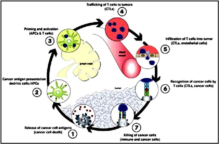
Figure 1. Basic physiological immunological-system defence against tumor cells. Roughly speaking, immunotherapy [35] drugs act as a feebback in all this system to enhance the immunological effect to destroy tumor cells during treatment, [Sketch form Google common images].
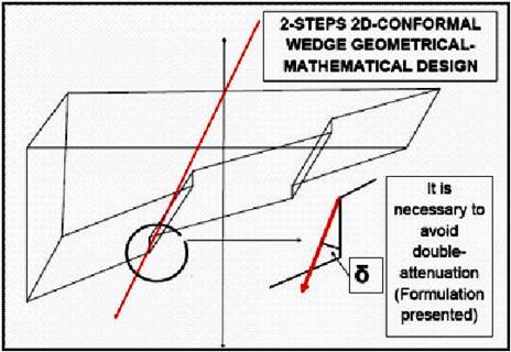
Figure 2. Basic sketch of a Conformal Wedge Filter [Casesnoves, 2005], presented in NEBEC New York Syracuse Conference, 2013, and later on, in the International Conference of International Institute of Informatics and Systemics, Orlando, Florida, 2014 [refs]. In Australian Health Service of New South Wales, they denominate it ‘stepping wedge’ and are carrying out extensive clinical trials actually for prostate cancer applications [3, 11-13].
In previous contributions, a special WF device, denominated Conformal Wedge Filter, [Casesnoves, 2005, first theoretical-mathematical design, Figure 2], was published in 2013-2015 in several articles and conferences [Casesnoves, 11-13]. Actually, extensive clinical trials are planned and carried out with the conformal wedge -denominated ‘stepping wedge filter’ [17]. These trials, for example, are intended to assess radiotherapy treatment post-surgery with conformal wedge filters in high-risk prostate cancer [17]. Software with Freemat and Matlab was developed in initial validation of the numerical design of the conformal wedge [11-13].
The 3D complete/original intellectual-property formulation for modelling of classical AAA algorithm was developed and invented by F Casesnoves during the Philadelphia OMICS Conference of Significant Advances in Biomedical Engineering, April 2015 –after his presentation of the radiotherapy wedge filter poster/article. Some authors [17] call it stepping wedge, but original invention was published by Casesnoves in 2014 [17]. The complementary 3D analytic geometry of the formulation and Omega Factor was created 11 days after the conference in Philadelphia, 2015.
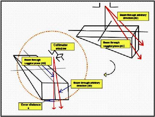
Figure 3. Graphical difference/error-path when using 2D approximation compared to 3D determination. If we take always the AEF approximation of Eq (1), in the sagittal plane, there is an error for less magnitude (blue brackett) in the path-distance through the wedge.
The AEF into the dose delivery integral equation, [Equation 1], is basically an exponential function of several variables, u, v, φ, and z. The primary calculations that were carried out to obtain more precision and accuracy with the AEF for dose delivery, previously [ref], can be improved further theoretically with this 3D formulation -in formulas, TPO construction, and pre-planning simulations.
Besides, the WF path of IMRT beamlets is got better in precision with a 3D spatial radiation-geometry into the planning system. It was intended here to develop the mathematics of AEF formulation towards the accurate match between previous calculations, [4-18], and the coordinates/parameters system of the generic AAA foundations [52-56]. The tumor inhomogeneities can be better sorted/geometrically-optimized with a more accurate AEF integral equation in 3D. What is more, the planning system programming/software, e. g. Eclipse from Varian, could be improved in practice with the addition of more precise and simplified 3D formulation. It was asserted in [56], that analytic solutions for AAA integral equation can reduce the planning system running time and be used with Fourier Transform optimization and convolution methods [56]. In other words, according to [56], saving computer time, storage space -use of pre-optimized data extensive tables instead large complete calculations. Complementary, to obtain useful graphical dose distributions, for example of PTVs, for continuous advances in dose delivery optimization. The formulation of this article is given to supplementary obtain realistic and objective advances, all in all, for inverse optimization of integral dose equation(s). That type of equations could be determined both analytically, mixed analytic-numerical, or explicitly numerically [4-13]. The essential exact path for WF was determined, In preceding publications, [4-13], with a coordinates system outlined for direct/simple analytical geometry calculations, that is, to set the incidence point of the beam and the output of the beam located at the lower WF surface. Afterwards to carry out the simple vectorial-norm distance. Ulmer and Harder, [56], and Figs. 2-3, found a 2D approximation, depending exclusively on u coordinate for the AEF, whose exponential frame is assumed for any other approximation in the literature, since the photon-beam attenuation models correspond classically to this type of formula. Therefore, there was a coordinates mismatch between the exact determination of the path and the u, φ, and z dependent approximation given in [56]. To sort this kind of mathematical disagreement, we worked out to determine an additional exact geometrical formulation, adding the default v coordinate to the classical AEF [56, 5-13]. Furthermore, this recent AEF (u, v, φ, z) adds complete consistency to the primary AEF (u, φ, z) of [56]. Provided with all these new determinations, this paper was intended to simulate water dose with the fundamental AAA integral equation. However, in this case with a new recent exact AEF for the exponential within the integrand with 3D and integral equation resolution. Analytical and computational geometry was applied for this objective and results were presented in successive mathematical-development stages. Programming software both in numerical analysis and computational geometry was presented with a series of well-defined computational images to prove accurately the results of the theoretical/geometrical calculations.
In summary, this article shows a number of improvements, mainly applicable in mathematical and geometrical optimization. Firstly, the geometry of the AEF has been extended to 3D with the implementation of the Omega Integral Exponential Factor in Eq 3. The mathematical proof of this consequence is put forward in the presented computational simulations and programming details. The simulations were made with realistic water-dosimetry values, tables, and LINAC parameters, [56]. The programming method is quite simple and can be used as a reference for more difficult formulation, that is, implemented in numerical methods. According to 3D imaging-programming results of simulations section, it is possible to assert that the objectives of this study have been promptly accomplished.
Figure 4. Sketch to show the necessary corrections in terms of precision for the foundational AEF in 2D. Classical 2D notation for wedge-path integral exponential factor. In Fig. 3 it is sketched the error that is taken using this approximation and in Eq 1 the recent solution for this exact path measurement is given in 3D. Parameters are included in Eq 1. As said, u, v are beam output size coordinates, z depth, L half wedge length, c output collimator-wedge surface distance, F total filter length, α wedge angle, φ beam/beamlet divergence angle. The constant µw is tabulated for different LINAC Photon-Energies.
Therefore, briefly, the complete results of this paper, in consequence, are related to numerical/analytical integral equation of AEF, simulations, mathematical formulation, numerical tables, and software development.
Finally, it is possible to assert that the AEF for the foundational AAA algorithm, in its integral equation, has been determined and proven with numerical-computational simulations and programming punctually. The mathematical proofs of this development have been rigorously checked both in formal geometrical analysis and realistic 3D simulations.
2. Determination of AEF 2D Demonstration with Further Precision Development
In this section we complete more extensively with sharp details the 2D geometrical determination of the AEF of Equation 1. In previous papers it was shown the proof for the broad part of the WF. Now the demonstration is extended with details for both parts of the WF, with more geometrical precision. The resulting formula for 2D in the thin half of the WF is shown as final equation, with new precision details related to [52-56, 9-13]. These details of precision are related to the divergence angle of the pencil-beam, φ, and compared with the results of Ulmer and Harder [52-56]. The starting formula is the classical equation,
![]() (1)
(1)
The mathematical-geometrical analysis for getting Eq 1, setting basic trigonometric principles, reads,
 (2)
(2)
To continue with distance decomposition, it is necessary to carry out a series of trigonometric calculations rather long, but convenient for future improved approximations in 3D, note that in this contribution we develop the method for the broad part of the wedge (with the change of φ notation for ɸ, in all the paper these notation angles are equivalent),
 (3)
(3)
Figure 5. (Enhanced in Apendix 1).-Basic Geometrical-mathematical demonstration sketch for Eq 1.
which is the numerical value of the exponential of Eqs 1 and 8, and has to be multiplied by the attenuation coefficient of the wedge material, μw. Therefore, the 2D approximation for wedge beam-path has been proven. However, it is mathematically convenient to show why a 3D calculation [2, 5], is demanding to improve the planning system software and avoid virtual underdosage (with the change of φ notation for ɸ, in all the paper these notation angles are equivalent). The mathematical development that follows in these section is based on trigonometric geometry, spatial-spherical trigonometry, triangle geometrical-proportional laws, and basic series differential development. The approximations that will be carried out take into account the primary terms of the series development, and the magnitude of the angles, usually rather small. It was intended to separate the large formulation in several parts in order to make the extent mathematical formulas quite understandable. As said, the notation is always the same with the exception of the nomenclature of one angle, (the change of φ notation for ɸ, in all the paper these notation angles are equivalent). It is also sharp that this geometrical development is not unique, that is, any other options and alternatives in spatial calculations to obtain the true value of Omega Factor constitute also a suitable approximation. In Fig. 3 it is sketched the difference between the 2D and 3D approximation with a graphical idea of the error. It was also intended a sharp simplification of the geometry in order to get a caption of the proportional segments of the pyramid corresponding to coordinates U1 and V1, and this can be seen in Figure 6 clearly, with specific details after the partition of the wedge filter into two halves. As it was shown in previous contributions, the 3D path D, through the wedge reads,
Figure 6. Pictured, sketch of the spatial-3D geometrical analysis carried out to determine Omega Factor [Ω]F for complete/exact resolution of the integral of [52-56]. It was intended a sharp simplification of the geometry in order to get a caption of the proportional segments of the pyramid corresponding to coordinates U1 and V1. The WF is divided into two halves to show the coordinates center better.
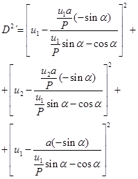 (4)
(4)
The recent determinations for the AEF formula in 2D, for the thin part of the wedge have resulted in further precision formulas. That complete mathematical geometrical development of WF thin part, will be presented in next contributions. The most important finding is that in the thin part of the wedge the angle φ becomes negative in the 2D AEF algorithm. This fact has consequences for the computational programming and simulations. Therefore, that is the reason to carry out in this paper the simulations of the broad part with and without Omega Factor. Here the resulting equation is shown, with this remark that in the thin part of the wedge the formulation is different. The AEF in 2D for the thin part of the wedge, up to that time, reads,
![]() (5)
(5)
It could seem, in terms of precision and errors, that it is not important, but it was found numerical differences when using this algorithm compared to the one with the positive sign of φ.
3. Mathematical-Geometrical Method
In this section it is proven geometrically, Fig. 2, the exact geometry of the beam path along the WF. We set a proportional irregular pyramid equations, and obtained the modification of the exponential AEF of [ref]. It was intended to link these geometrical proportions to the classical exponential of the AEF. Then, u coordinate in [refs] depends on φ1 and v depends on φ2 in this development, because φ2 angle is linked to coordinate v. Apart from that, it is included the z coordinate with WF parameters such as α and L. The 3 dimensions equation is complete, as shown in Eqs 4, 7. Coordinates U1 and V1 are not the u, v coordinates at delivery point (x, y, z) and included into the integral equation. But geometrically are directly linked to these u, v values by means of angles φ1 and φ2, Fig. 6. Details of the mathematical proof are in Eqs 1-8, with the definition of the [Ω]F Factor and the [Ω]F1 one. According to Fig. 6 and all these conditions, it is asserted,
Definition 1.-Geometrical Omega Factor, namely, [Ω]F, is defined as a numerical coefficient that transforms the 2D approximated integral attenuation factor, [AEF]Approximated, into an exact attenuation factor, [AEF]Exact.
Proposition 1.- Geometrical Omega Factor, namely, [Ω]F, can be expressed in multiple geometrical-algebraic forms, and one suitable for integration is,
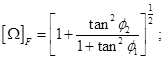 (6)
(6)
Proof: geometrical according to Fig. 6 and Equations 1, 2, 6.
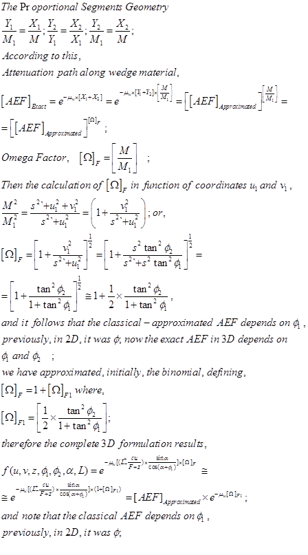 (7)
(7)
Proposition 2. -The limit of the [Ω]F when we approach the angle φ2 to zero, is 1, and therefore coordinate v to zero, converts the [AEF]Exact into the [AEF]Approximated.
Proof:
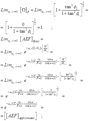 (8)
(8)
Proposition 3.-Omega Factor [Ω]F can be simplified/approximated numerically with any kind of binomial/series approximation and a simple one is,
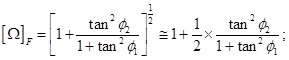
with notation
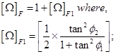 (9)
(9)
Proof: direct application of binomial theorem.
Proposition 4.- Omega Factor [Ω]F increases in direct proportion to the beam-divergence angle magnitude increase. In particular, when φ1 ≤ φ2 or when φ1 and φ2 are equal. This holds sharply for divergence angles ≤ 45°.
Proof: there are several ways to simply prove this proposition, e.g., series development, here we use the easiest,
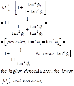 (10)
(10)
The proof can be extended also on the inequal conditions of φ2 and φ1. Recall that this proposition is related to beam-divergence angles ≤ 45°.
This section is concluded with the most important finding of the contribution, which is the 3D Omega Factor, whose computational simulations and comparisons with classical 2D AEF will set sharply the precision differences to the dosimetry in water of WF integral equation with 2D AEF.
4. Integral Resolution and Further Mathematical Development
I this section the basic formulas for the complete integral equation solution with Omega Factor are explicitly detailed, with a few mathematical complements for sharp understanding.
The integral equation for AAA in water with 2D AEF and without 3D Omega Factor [Ω]F reads,
 (11)
(11)
And the modified fluence,
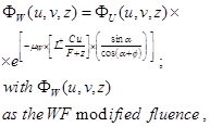 (12)
(12)
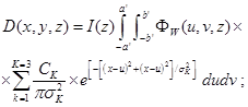
The integral equation for AAA in water with 3D AEF Omega Factor [Ω]F is as follows,
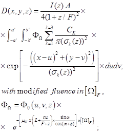 (13)
(13)
The solution, exact, complete, and analytical of this integral equation (Casesnoves, 2015, April, Philadelphia), reads,
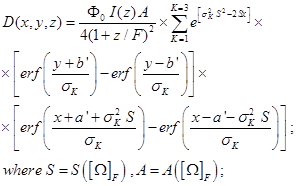 (14)
(14)
Constants are given following the pevious equations. This formula is an Omega Factor correction from the Equations 11-15 of classical [52-56]. The S and A variables depend on Omega factor and will be mathematically developed in numerical computation programming and graphics sections. This integral equation complete analytical solution will be correctly simulated in dosimetry-matrices from 100x100 dimensions to 1500x1500 dimensions in the following section, and compared with simulations of Equations 11-15 of classical AEF [52-56].
5. Computational Simulations and Graphics
This section deals with general information of the simulations series that were carried out and the principal images and settings for the generation of the programming codes. It is specifically focused on the sharp presentation of the data and formulation implemented in the software, and the overview of the technical details for the computational radiotherapy simulations. The principal objective of the simulation programming was to demonstrate that the inclusion of the Omega Factor, [Ω]F, into the integral equations creates a clear difference in magnitude order of the resulting delivery dose in water. This implies that both the statements/assertions and the numerical-geometrical calculus done are precise and correct. In this order, the presentation of the numerical data in tables constitutes an essential clarification complement to support the previous formulation, and the validity of the simulation imaging results obtained. Table 2 shows the main numerical data for the imaging, and the series of figures are explained with computational details instead to include written information in the section properly. The magnitude of Omega factor is about 1.12, for a WF of 15° (degrees), and increases with the WF angle till 45°. Note that this apparently small value of Omega Factor becomes propagated by multiplication other constants in formulation and the result is a change of 3D dose delivery magnitude as shown in imaging simulations. It is imperative make clear that standard magnitudes of WF degree angles vary today in a rather wide range depending of the type of LINACs and the functionality of the Radiation Oncology Station.
Table 2. Main computational simulations data and formulation.
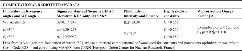
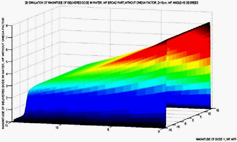
Figure 7. Simulation Graphics of Matlab, directly taken from the debug of the program. Omega Factor is not included in the AAA algorithm. Here the matrices dimensions were about 100 x 100. The surface takes the right sloping variation along the X direction.
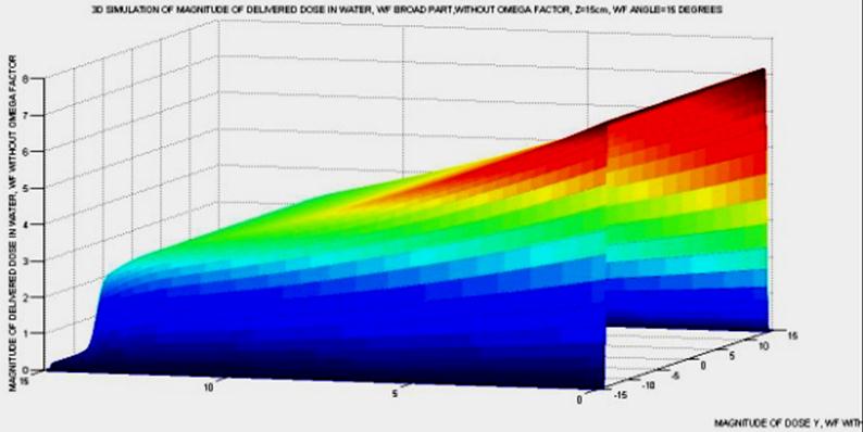
Figure 8. Simulation Graphics of Matlab, but in jpg format, directly taken from the debug of the program, but in a different angle. Omega Factor is not included in the AAA algorithm. Here the matrices dimensions were about 100 x 100. The surface takes the right sloping variation along the X direction.
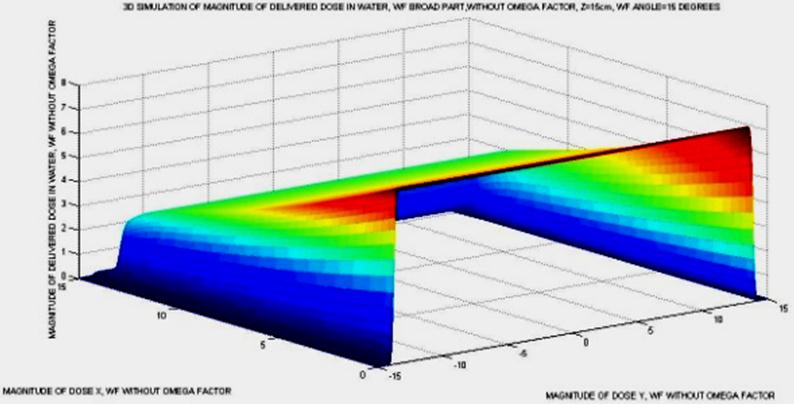
Figure 9. Simulation Graphics of Matlab, in jpg, directly taken from the debug of the program, but in a different angle. Dose magnitude along Y axis does not vary at all. Omega Factor is not included in the AAA algorithm. Here the matrices dimensions were about 100 x 100. The surface takes the sloping variation along the X direction. The surface variation along the Y axis is completely straight.
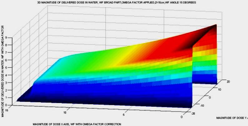
Figure 10. Simulation Graphics of Matlab, in jpg, directly taken from the debug of the program, in a lateral angle. Dose magnitude along Y axis vary slightly, and that was seen with imaging cursor of the program. That is if we take the cursor along several sliced lines, dose values vary slightly in Y direction, which is different from simulations without Omega Factor. Here the matrices dimensions were about 1000 x 1000 to define better the image. Running time was around 15 seconds. The surface takes the curved variation along the X direction, and this is a significant difference with AEF without Omega Factor.
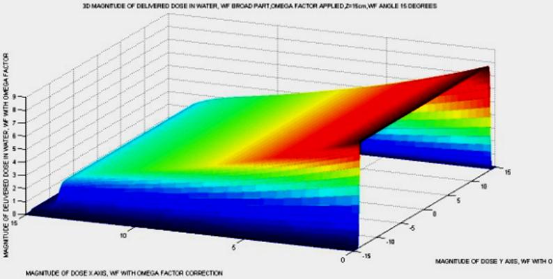
Figure 11. Simulation Graphics of Matlab, in jpg, directly taken from the debug of the program, but in a different oblique angle. Dose magnitude along Y axis does not vary at all, only slightly. Omega Factor is included in the AAA algorithm. Here the matrices dimensions were about 1100x1100. The surface takes the variation along the X direction, in curved slope.
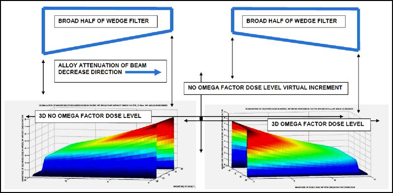
Figure 12. Computational-Graphical simulation-proof of virtual dose error caused by 2D approximated integral equation solution. This simulation is important, because it proves sharply the virtual dose error that is given by the AAA algorithm when using AEF in 2D. That is, the planner system calculates a higher dose compared to the true dose, and this error causes under-dosage on the tumor. On the opposite, 3D planning with Omega Factor results in more precise dose for radiotherapy optimization -with the significant mention that all these calculations and simulations are carried out in water with the foundation AAA model. The simulation is done in the thick part of the wedge, because recent advances have been useful to find a difference in the sign of angle φ1 for the thin half of the WF –this extent analytical-geometry calculation will be explained and simulated in next contributions. The most important objective of this article was to demonstrate the correct approximations and mathematical development together with the computational proof that validates the difference of magnitude between 2D AAA in water and 3D with Omega Factor dosimetry in the same conditions.
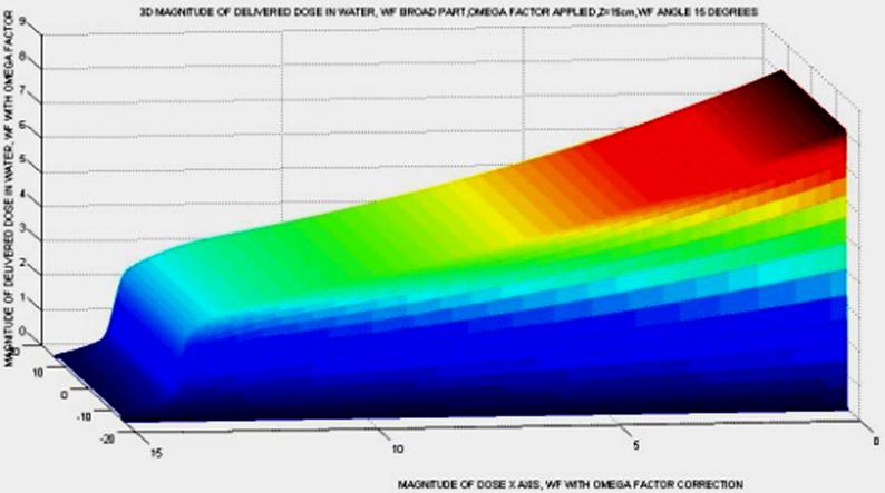
Figure 13. Simulation with view of dosimetry distribution at the thickest part of the half WF. The attenuation of the photon-beam or pencil beam is maximum and Omega Factor is applied in computed algorithm. It is clear the softly curved slope of the 3D dose distribution, which agrees to the sectional slices that give the classical 2D-curve representation of the WF dose delivery in the literature. To carry out this simulation it was necessary to increase the discrete number of points for the dose matrices, reaching matrices dimensionss of 1000x1000. We remark that the fluence absolute value was set arbitrarily as 103 but results for experimental data conclude in the same profile.
For a complete caption of numerical data developed, the Appendix 3 gives sufficient information about the calculations to be computationally implemented.
The starting formulas are the integral equation and its exact solution with the [Ω]F included, beginning with previous equations,
(15)
And the specification of the parameters A and S according to Omega factor modifications are as follows,
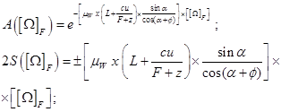 (16)
(16)
The positive sign is for the broad part of the WF, the object of interest of these simulations. Conversion and mathematical changes to obtain these adaptable modifications to get the analytical integral equation solution(s) come from [1-13, 56].
In the following, we pass on direct presentation of 3D programming images of the implementation of these formulas to prove graphically the results of this further-precision dosimetry determinations.
In summary, it was included a series of 3D simulations, in contrast with usual research of dosimetry in wedges developed in 2D. The difference of dose between AAA 2D and AAA 3D (Omega Factor) becomes sharply evident and clearly proven. In other words, those geometrical and algebraic calculations carried out in previous sections find here the computational corroboration and verification definitely.
6. Computational Programming with Comparative Implementation of Algorithms and Formulas
This section comprise specific technical explanations about the software designed to implement mainly the 3D WF surface representations and the complexity difficulties of dosimetric matrices that have to be adapted on the integral equation solution. The difficulties of programming this type of algorithm, AAA, is rather more conceptual than technical. The matrix point-by-point element-wise dose calculations and summatory impose a reshape of the dosimetry matrices to perform multiplications and, later, to be included into the 3D imaging subroutine. In contrast with previous contributions with Free Software, [refs], and with comparative intentions also, the numerical representations were made with Matlab 2009-2010 License version. Previously, Freemat 4.1 (General Public License Samit Basu), was successfully implemented with acceptable computational results [ref]. Nevertheless, Freemat and Matlab are almost equivalent related to curve fitting, graphics, and optimization subroutines, with a number of specific differences.
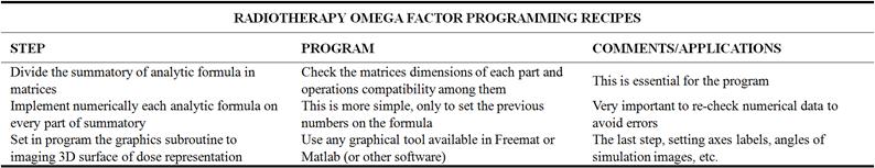
In Table 3 it is shown formulation and more specific programming recipes of the number of codes that have been properly designed for AAA generic algorithm in water. Just the same exposition of technical formulas and data for this section. In other words, the details are expressly included briefly at Table 3 for concise and clear learning.
Table 3. Specific numerical codes and omega factor programming.
7. Software-Programming Development with Specific Algorithm Differentiation
This section is focused only on the method to differentiate in programming the AAA implementation in the generic algorithm to the corresponding one of the AAA AEF with the Omega Factor included. The technique to set the differences has been explained previously. Here a numerical example of the analytic resolution that was calculated is presented for z=15cm, 18 MeV data of X rays of a Siemens Mevatron KD2, and simulated fluence of absolute magnitude 103. WF angle is 15°, and F =100cm. Output collimator LINA window is set 12x12 cm2. Algorithms, for C2 and Omega Factor read,
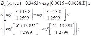 (17)
(17)
It is straight forward to guess that a wide number of numerical techniques can be used both for programming these error functions product or approximate all the functions with precise and almost equivalent formulas. All these questions are for next contributions and at present we show these series of numerical 3D imaging results.
8. Discussion and Conclusions
The new contribution of this article is focused on the extension to 3D of the AEF in the AAA generic formulation [56]. Mathematical, algebraic, and analytical geometry demonstrations were carried out.
A series of programming simulations with the Omega AEF Integral Factor were shown with sharp explanations about the computational implementation method. Errors of those simulations have been also presented and analyzed. Future developments and utility of this new formulation have been explained extensively, in special reference to radiotherapy treatment adjuvant to chemo/immunotherapy –with modern and sufficient number of references.
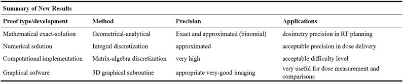
In Table 4, a summary of the paper results highlights are included briefly. The framework of this paper can be considered a simple and accurate first practical test for the Omega AEF Integral Factor and AAA primary integral equation. In next publications tissue inhomogeneities complementary to these initial advances will be examined and developed. This Table 4 with Figures 14 and 15 corroborate sharply all the achievements got in this new contribution.
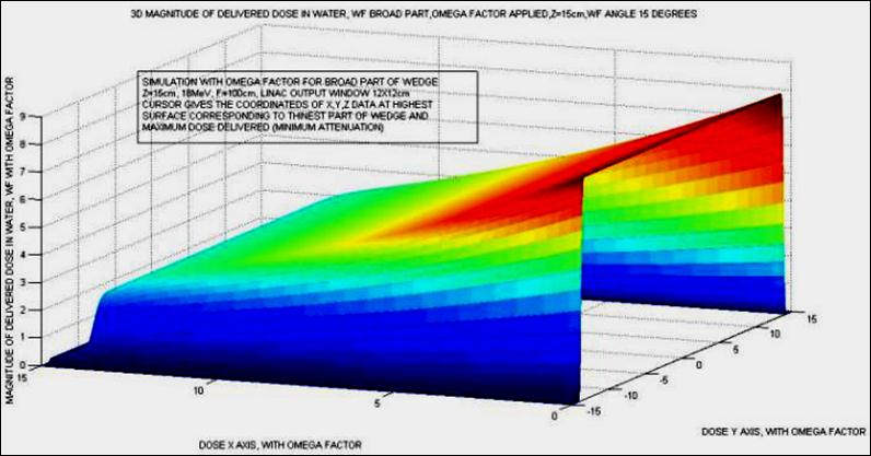
Figure 14. 3D summary, pictured, of the results of computational implementation of Omega Factor. The simulation parameters are detailed, text box pictured inset, with data of the simulation. It was deliberatedly taken this oblique projection to show the differences between the half zone of WF attenuation (higher dose) and the broad WF extreme dose attenuation (lowest dose, highest photon-beam attenuation). Matrices dimensions of dose values are higher than 1200x1200.
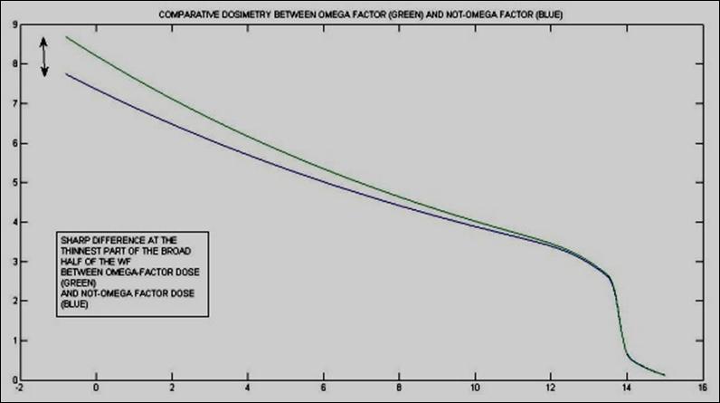
Figure 15. Comparative-Double Simulation with 2D view of dosimetry distribution at the thickest part of the half WF, green curve is Omega Factor implemented into integral equation and blue (lower) curve corresponds to integral equation classical 2D solution [56]. Important dosimetrical consequences/observations can be guessed from this simulation. First, the magnitude difference between both algorithms, which is rather intuitive without cursor in 3D surface representations, is sharply set in this saggital simulation at the half part of the WF. Secondly, but not less important, is that dosimetric curves with/without Omega Factor tend to converge towards the thickness increase direction of the wedge –and in fact this property has TPO applications. The mathematical-geometrical demonstration to explain this divergence-phenomenon will be presented in next contributions. We recall that a Fluence value of 103 was used for this simulation, and other values, numerically correctly guessed, would result in the same contundent proof.
Table 4. Highlights and summary of new results.
9. Scientific Ethics Standards and Acknowledgements
This study was carried out, and their contents are done according to the European Union Technology and Science Ethics. Reference, ‘European Textbook on Ethics in Research’. European Commission, Directorate-General for Research. Unit L3. Governance and Ethics. European Research Area. Science and Society. EUR 24452 EN. This study was completely done by the author, the software, calculations, images, mathematical propositions and statements, reference citations, and text is original for the author. This publication is submitted in United States exclusively to one journal. This article contains also unique numerical data and special images. The principal sketches were made originally, and the figures, tables, or data that correresponds to previous papers is properly clarified. When anything is taken from a source, it is properly recognized [58].
This contribution is dedicated to my parents with gratitude and sincere love. They have given me the life and my education.
Appendix 1
2D geometrical development of AEF in the broad part of the wedge filter.
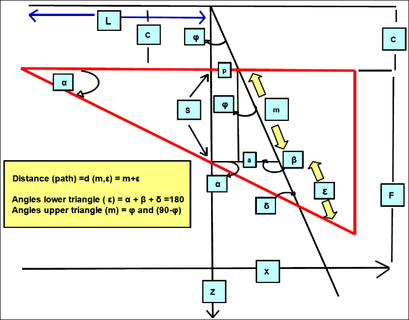
Figure 16. (Enhanced in Apendix 1).-Basic Geometrical-mathematical demonstration sketch for Eq (1). The thin part obeys different equations an dcalcukations and will be explained in following contributions.
Appendix 2
Series of complete computational-imaging dosimetry distribution for WF without taking recent φ angle geometrical calculations
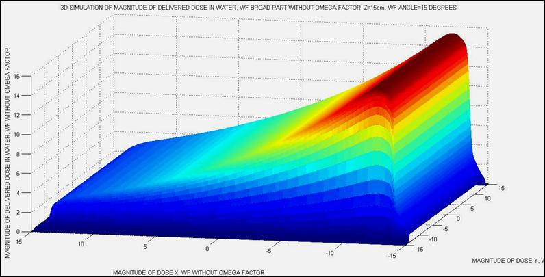
Figure 17. Appendix 2 (Different software).-Complete dose delivery computational implementation without Omega Factor z=15cm. Dosimetry matrices dimensions are less than 100 x 1000. Programming conditions are different to extend all the algorithm to the complete volume of wedge and obtain dosimetry distribution in 3D.
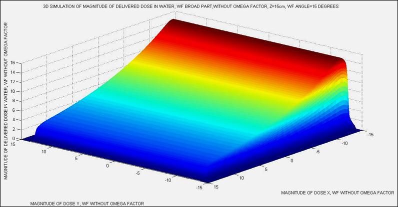
Figure 18. Appendix 2, (Different software).-Different angle to show the effect of the broadpart of the wedge. Complete dose delivery computational implementation without Omega Factor z=15cm. Dosimetry matrices dimensions are less than 100 x 1000.
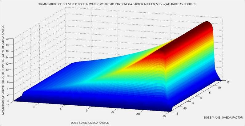
Figure 19. Appendix 2.-Complete dose delivery computational implementation with Omega Factor z=15cm. Dosimetry matrices dimensions are less than 100 x 1000. It is clear the magnitude of dose difference with the classical 2D AEF. Programming conditions are different, and even something more difficult to extend all the algorithm to the complete volume of wedge and obtain dosimetry distribution in 3D with inclusion of Omega Factor.
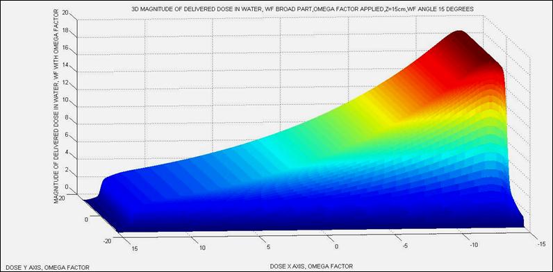
Figure 20. Appendix 2.-Complete dose delivery computational implementation with Omega Factor, lateral angle, z=15cm. Dosimetry matrices dimensions are 1800 x 1800. It is clear the magnitude of dose difference with the classical 2D AEF. Programming conditions are different, and even something more difficult to extend all the algorithm to the complete volume of wedge and obtain dosimetry distribution in 3D with inclusion of Omega Factor.
Appendix 3
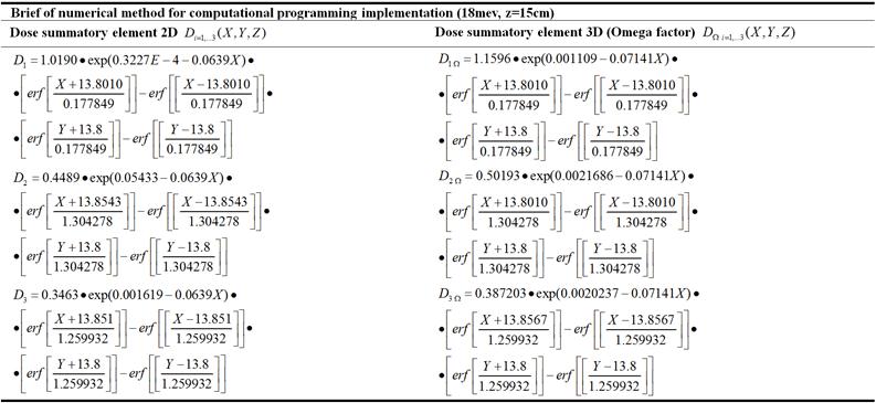
Table 5. Brief of numerical calculations to carry out a series of 3D simulations provided the proper implementation of these values in matrix algebra form. Although the factors differences between 2D and 3D seem to be non-significative, the results in both computational imaging and dose magnitude set a sharp difference in dose delivery for Omega Factor compared to 2D classical integral solution. The figures of first constant in each formula can give a sharp learning of the Omega factor influence in the resulting dosimetry magnitude.
References
- Casesnoves, F. 'Exact/Approximated Geometrical Determinations of IMRT Photon Pencil-Beam Path Through Alloy Static Wedges in Radiotherapy Using Anisothropic Analytic Algorithm (AAA)’. Peer-reviewed ASME Conference Paper. ASME 2011 International Mechanical Eng Congress. Denver. USA. IMECE2011-65435. 2011.
- Casesnoves, F. 'Geometrical Determinations of Limit angle (LA) related to maximum Pencil-Beam Divergence Angle in Radiotherapy Wedges’. Peer-reviewed ASME Conference Paper. ASME 2012 International Mechanical Eng Congress. Houston. USA. IMECE2011-65435. 2011.
- Casesnoves, F 'A Conformal Radiotherapy Wedge Filter Design. Computational and Mathematical Model/Simulation’ Casesnoves, F. Peer-Reviewed Poster IEEE (Institute for Electrical and Electronics Engineers), Northeast Bioengineering Conference. Syracuse New York, USA. April 6th 2013. Peer-Reviewed Poster Session on 6th April 2013. Sessions 1 and 3 with Poster Number 35. Page 15 of Conference Booklet.
- Casesnoves, F. Mathematical and Geometrical Formulation/Analysis for Beam Limit Divergence Angle in Radiotherapy Wedges. Peer-Reviewed International Engineering Article. International Journal of Engineering and Innovative Technology (IJEIT) Volume 3, Issue 7, January 2014. ISSN: 2277-3754 ISO 9001: 2008 Certified. http://www.ijeit.com/archivedescription.php?id=27.
- Sharma, SC. Beam Modification Devices in Radiotherapy. Lecture at Radiotherapy Department, PGIMER. India. 2008.
- Casesnoves, F.'Geometrical determinations of IMRT photon pencil-beam path in radiotherapy wedges and limit divergence angle with the Anisotropic Analytic Algorithm (AAA)' Casesnoves, F. Peer-Reviewed scientific paper, both Print and online. International Journal of Cancer Therapy and Oncology 2014; 2 (3): 02031. DOI: 10.14319/ijcto.0203.1
- Casesnoves, F. ‘Radiotherapy Conformal Wedge Computational Simulations and Nonlinear Optimization Algorithms’. Casesnoves, F. Peer-reviewed Article, Special Double-Blind Peer-reviewed paper by International Scientific Board with contributed talk. Official Proceedings of Bio- and Medical Informatics and Cybernetics: BMIC 2014 in the context of The 18th Multi-conference on Systemics, Cybernetics and Informatics: WMSCI 2014 July 15 - 18, 2014, Orlando, Florida, USA.
- Casesnoves, F. ‘Large-Scale Matlab Optimization Toolbox (MOT) Computing Methods in Radiotherapy Inverse Treatment Planning’. High Performance Computing Meeting. Nottingham University. January 2007.
- Casesnoves, F. ‘A Computational Radiotherapy Optimization Method for Inverse Planning with Static Wedges’. High Performance Computing Conference. Nottingham University, January 2008.
- Casesnoves, F. ‘ Radiotherapy Conformal Wedge Computational Simulations, Optimization Algorithms, and Exact Limit Angle Approach ‘. International Journal of Scientific Research in Science, Engineering and Technology. Publication Details, Published in: Volume 1 | Issue 2 | March-April – 2015 Date of Publication Print ISSN Online ISSN Date 2015-04-25 2395-1990 2394-4099. Journal Print ISSN: 2395-1990 | Online ISSN: 2394-4099. Page(s) Manuscript Number Publisher 353-362. IJSRSET152259 Technoscience Academy - See more at: http://ijsrset.com/IJSRSET152259.php#sthash.GXW6At87.dpuf. http://ijsrset.com/IJSRSET152259.php. Print ISSN: 2395-1990 Online ISSN: 2394-4099.
- Casesnoves, F. ‘ Radiotherapy Standard/Conformal Wedge IMRT-Beamlet Divergence Angle Limit Exact Method, Mathematical Formulation, and Bioengineering Applications’. International Article-Poster. Published in Proceedings of Conference. 41st Annual Northeast Bioengineering Conference. Rensselaer Polytechnic Institute. Troy, New York USA, April 17-19, 2015.
- .-Casesnoves, F.‘ Radiotherapy Standard/Conformal Wedge IMRT-Beamlet Divergence Angle Limit Exact Method, Mathematical Formulation, and Bioengineering Applications’. IEEE (Institute for Electrical and Electronics Engineers), International Article-Poster. Published in http://ieeexplore.ieee.org/xpls/abs_all.jsp?arnumber=7117152. Date of Conference: 17-19 April 2015 Page(s): 1 - 2 Print ISBN: 978-1-4799-8358-2 INSPEC Accession Number: 15203213.
- Casesnoves, F. ABSTRACT-JOURNAL. ‘ Radiotherapy Standard/Conformal Wedge IMRT-Beamlet Divergence Angle Limit Exact Method, Mathematical Formulation’. International Conference on Significant Advances in Biomedical Engineering. 252nd OMICS International Conference. April 2015. Volume 5, Issue 1. ISSN 2155-9538. Page 77. Philadelphia USA.
- Ahnesjö A., Saxner M., A. Trepp. 'A pencil beam model for photon dose calculations'. Med. Phys. 19, pp 263-273, 1992.
- Brahme, A. 'Development of Radiation Therapy Optimization'. Acta Oncologica Vol 39, No 5, 2000.
- Bortfeld, T, Hong T, Craft, D, Carlsson F. 'Multicriteria Optimization in Intensity-Modulated Radiation Therapy Treatment Planning for Locally Advanced Cancer of the Pancreatic Head'. International Journal of Radiation Oncology and Biology Physics. Vol 72, Issue 4.
- Brown, Bernardette, and all members of Research Group. ‘Clinician-led improvement in cancer care (CLICC) -testing a multifaceted implementation strategy to increase evidence-based prostate cancer care: phased randomised controlled trial - study protocol’. Implementation Science 2014, 9: 64.
- Bortfield, T. ‘IMRT: a review and preview’. Phys. Med. Biol. 51 (2006) R363–R379.
- Censor Y, and S A Zenios. 'Parallel Optimization: Theory, Algorithms and Applications'. UOP, 1997.
- Casesnoves, F. ‘Determination of absorbed doses in common radiodiagnostic explorations’.5th National Meeting of Medical Physics. Madrid, Spain. September 1985. reatment Planning’. Kuopio University. Radiotherapy Department of Kuopio University Hospital and Radiotherapy Physics Group. Finland. 2001.
- Casesnoves, F. ‘Large-Scale Matlab Optimization Toolbox (MOT) Computing Methods in Radiotherapy Inverse Treatment Planning’. High Performance Computing Meeting. Nottingham University. Geometrical and analytical geometry developments with equations of this poster were applied. January 2007.
- Casesnoves, F. ‘A Computational Radiotherapy Optimization Method for Inverse Planning with Static Wedges’. High Performance Computing Conference. Spherical-3D-Geometrical and analytical geometry developments of this poster were applied Nottingham University. January 2008.
- Casesnoves, F 'Exact/Approximated Geometrical Determinations of IMRT Photon Pencil-Beam Path Through Alloy Static Wedges in Radiotherapy Using Anisothropic Analytic Algorithm (AAA)' peer-reviewed ASME Conference Poster and Lecture. Proceedings of ASME 2011 IMECE (International Mechanical Engineering Conference) Conference. Denver, Nov 2011. CO, USA. 2011.
- Casesnoves, F 'Geometrical Determinations of Limit Angle (LA) related to Maximum Pencil-Beam Divergence Angle in Radiotherapy Wedges' Casesnoves, F. Peer-reviewed ASME Conference Poster and Talk. ASME 2012 International Mechanical Engineering Congress. Houston. Nov 2012. USA. IMECE2012-86638.
- Casesnoves, F.'A Conformal Radiotherapy Wedge Filter Design. Computational and Mathematical Model/Simulation’. Peer-Reviewed Poster and Presentation IEEE (Institute for Electrical and Electronics Engineers), Northeast Bioengineering Conference. Syracuse New York, USA. Presented in the Peer-Reviewed Poster Session on 6th April 2013. Sessions 1 and 3 with Poster Number 35. Page 15 of Conference Booklet. April 6th 2013.
- Casesnoves, F. 'Geometrical determinations of IMRT photon pencil-beam path in radiotherapy wedges and limit divergence angle with the Anisotropic Analytic Algorithm (AAA)'. Peer-Reviewed scientific paper, both Print and online. International Journal of Cancer Therapy and Oncology 2014; 2 (3): 02031. Additional version in Academia.edu DOI: 10.14319/ijcto.0203.1
- Casesnoves, F. ‘Radiotherapy Conformal Wedge Computational Simulations and Nonlinear Optimization Algorithms’. Casesnoves, F. Peer-reviewed paper with 15 minutes Lecture and Discussion, Special Double-Blind Peer-reviewed paper by International Scientific Board with contributed talk. Official Proceedings of Bio- and Medical Informatics and Cybernetics: BMIC 2014 in the context of The 18th Multi-conference on Systemics, Cybernetics and Informatics: WMSCI 2014 July 15 - 18, 2014 – Orlando, Florida, USA.
- Censor, Y. 'Mathematical Optimization for the Inverse problem of Intensity-Modulated Radiation Therapy'. Laboratory Report, and complementary notes and appendices. Department of Mathematics, University of Haifa, Israel, 2005.
- Capizzello A, Tsekeris PG, Pakos EE, Papathanasopoulou V, Pitouli EJ. 'Adjuvant Chemo-Radiotherapy in Patients with Gastric Cancer'. Indian Journal of Cancer, Vol 43, Number 4. 2006.
- Tamer Dawod, E. M. Abdelrazek, Mostafa Elnaggar, Rehab Omar. Dose Validation of Physical Wedged symmetric Fields in Artiste Linear Accelerator. International Journal of Medical Physics, Clinical Engineering and Radiation Oncology, 2014, 3, 201-209. Published Online November 2014 in SciRes.
- Do, SY, David A, Bush Jerry D Slater. 'Comorbidity-Adjusted Survival in Early Stage Lung Cancer Patients Treated with Hypofractioned Proton Therapy'. Journal of Oncology, Vol 2010.
- Ehrgott, M, Burjony, M. 'Radiation Therapy Planning by Multicriteria Optimization'. Department of Engineering Science. University of Auckland. New Zealand.
- Ezzel, G A. 'Genetic and geometric optimization of three dimensional radiation therapy treatment planning'. Med. Phys. 23, 293-305.1996.
- Effective Health Care, Number 13. 'Comparative Efectiveness of Therapies for Clinically Localized Prostate cancer'. 2008.
- Silvia C. Formenti, Sandra Demaria. Combining Radiotherapy and Cancer Immunotherapy: A Paradigm Shift Silvia C. Formenti, Sandra Demaria. J Natl Cancer Inst; 2013; 105: 256–265.
- Haas, O. C. L. 'Radiotherapy treatment planning, new systems approaches'. Springer Engineering. 1998.
- Hansen, P. 'Rank-deficient and discrete ill-posed problems: numerical aspects of linear inversion'. SIAM monographs on mathematical modelling and computation, 1998.
- Hashemiparast, SM, Fallahgoul, H. Modified Gauss quadrature for ill-posed integral transform. International Journal of Mathematics and Computation. Vol 13, No. D11. 2011.
- Isa, N. Evidence based radiation oncology with existing technology. Reports of practical oncology and radiotherapy 1 9 (2 0 1 4) 259–266.
- Johansson, K-A, Mattsson S, Brahme A, Turesson I. ' Radiation Therapy Dose Delivery'. Acta Oncologica Vol 42, No 2, 2003.
- Khanna P, Blais N, Gaudreau P-O, Corrales-Rodriguez L, Immunotherapy Comes of Age in Lung Cancer, Clinical Lung Cancer (2016), doi: 10.1016/j.cllc.2016.06.006.
- Kufer, K. H. Hamacher HW, Bortfeld T.. ' A multicriteria optimisation approach for inverse radiotherapy planning'. University of Kaiserslautern, Germany.
- Kirsch, A. 'An introduction to the Mathematical Theory of Inverse Problems'. Spinger Applied Mathematical Sciences, 1996.
- Luenberger D G. 'Linear and Nonlinear Programming 2nd edition'. The subsequent editions were studied also. Problems solutions published and problems solutions made by author in Nonlinear Optimization course (Eastern Finland University, 1999, excellent mark 9 out to 12) were applied. Addison-Wesley, 1989.
- Moczko, JA, Roszak, A. 'Application of Mathematical Modeling in Survival Time Prediction for Females with Advanced Cervical cancer treated Radio-chemotherapy'. Computational Methods in science and Technology, 12 (2). 2006.
- Numrich, RW. 'The computational energy spectrum of a program as it executes'. Journal of Supercomputing, 52. 2010.
- Ragaz, J, and collaborators. 'Loco-regional Radiation Therapy in Patients with High-risk Breast Cancer Receiving Adjuvant Chemotherapy: 20-Year Results of the Columbia Randomized Trial'. Journal of National Cancer Institute, Vol 97, Number 2. 2005.
- Steuer, R. 'Multiple Criteria Optimization: Theory, Computation and Application'. Wiley, 1986.
- Spirou, S. V. and Chui, C. S. 'A gradient inverse planning algorithm with dose-volume constraints'. Med. Phys. 25, 321-323.1998.
- Sharma, SC. 'Beam Modification Devices in Radiotherapy'. Lecture at Radiotherapy Department, PGIMER. 2008.
- Sievinen J, Waldemar U, Kaissl W. AAA Photon Dose Calculation Model in Eclipse™. Varian Medical Systems Report. Rad #7170A. Complementary, several industrial Varian Reports were studied and applied.
- Ulmer, W, and Harder, D. 'A triple Gaussian pencil beam model for photon beam treatment planning'. Med. Phys. 5, 25-30, 1995.
- Ulmer, W, and Harder, D. 'Applications of a triple Gaussian pencil beam model for photon beam treatment planning'. Med. Phys. 6, 68-74, 1996.
- Ulmer, W, Pyyry J, Kaissl W. 'A 3D photon superposition/convolution algorithm and its foundation on results of Monte Carlo calculations'. Phys. Med. Biol. 50, 2005. Complementary Lab Reports of this paper were studied and applied, mainly in LINAC parameters, geometry and photon-beam physical characteristics.
- Ulmer, W. Laboratory Report. Phys. Med. Biol. 50, 2005.
- Ulmer, W, and Harder, D. 'Applications of the triple Gaussian Photon Pencil Beam Model to irregular Fields, dynamical Collimators and circular Fields'. Phys. Med. Biol. 1997.
- Ulmer, W, Schaffner, B. 'Foundation of an analytical proton beamlet model for inclusion in a general proton dose calculation system'. Radiation Physics and Chemistry, 80. 2011.
- European Textbook on Ethics in Research’. European Commission, Directorate-General for Research. Unit L3. Governance and Ethics. European Research Area. Science and Society. EUR 24452 EN.


