
International Journal of Electronic Engineering and Computer Science, Vol. 1, No. 2, November 2016 Publish Date: Oct. 19, 2016 Pages: 65-69
Analysis Recloser as Reader Flow Disturbances in SUTM 20KV Feeders Tambak Wedi (Electricity Company) UPJ Kenjeran
Efrita Arfah Zuliari*, Karyono
Electrical Engineering Department, Institut Teknologi Adhi Tama Surabaya, Indonesia
Abstract
The distribution network of 20 kV feeders Tambak Wedi (Electricity Company) Network Services Unit (UPJ) Kenjeran, a channel 3 phase, form a network is voltage loop with the operation of 20 kV with a channel length of 25.40 Kilo Meter Circuit (KMS). Risk channels is their momentary interruption caused by kites, trees, rain, high winds, damage to equipment, planned outages and other causes. Disorders overcurrent, short circuit current phase and short circuit to ground are the dominant common. Anticipation is best to install equipment overcurrent protection or short circuit in the Medium Voltage Air Channel (SUTM) or so-called Recloser, because Recloser able to secure a momentary fault current is equal to 2986.2687 Ampere. Disruption phase and voltage can be reentered if considered a nuisance is not permanent as well as narrowing blackout radius. In the end consumers of electricity users will comfortably enjoy the presence of continuous electricity.
Keywords
Recloser, Current Readers, Disorders, Network 20 KV
Received: August 18, 2016
Accepted: September 18, 2016
Published online: October 19, 2016
@ 2016 The Authors. Published by American Institute of Science. This Open Access article is under the CC BY license. http://creativecommons.org/licenses/by/4.0/
Contents
1. Introduction
The distribution network of Electricity Company network service unit (UPJ) Kenjeran, in the form of three-phase airway are examined by two substations namely KENJERAN substation which is located at Jalan Karang Asem and substation UJUNG in each feeder consists of several sections equipped with an assortment of tools including breakers and safety Load Break Switch (LBS), Vacuum Switch (VS), Potential Transformer (PT) Current Transformer (CT) and Fuse Cut out brand (FCOb).
Medium voltage air channels 20 kV prone to occur interruption Over Current Relay (OCR). Ground Fault Relay (GFR) is a disorder due to load/interference between phase and phase to ground disturbance. Of the disorder, the relay can read the fault current only at the substation because the tools are installed in air ducts medium voltage a breaker which is operated manually and can not break the load when the feeder disruption and therefore Electricity Company Network Services Unit (UPJ) Kenjeran installing protective devices called Recloser. Recloser can read currents disturbances in the form of Over Current Relay (OCR) and Ground Fault Relay (GFR). If interference occurs in feeders the Recloser will open automatically and read the fault current.
Fault current of the short circuit such as Over Current Relay (OCR) and Ground Fault Relay (GFR) which occurs within a network of 20 kV electrical system can be calculated using the formula the Law of Ohm (Ω). By calculating the source impedance, calculates reactance of power transformer, reactance sequence of positive and negative, zero sequence reactance, impedance counting of feeders, equivalent impedance then calculate the current disturbance.
Research on Recloser to reduce interference on the electricity had been done by previous researchers, among others: Lorenzo et al. (2015), Mohsen (2012), and Aleksander Pregelj, However, research on the use Recloser to reduce electrical interference especially at Electricity Company has not been done.
With attached Recloser in feeder Tambak Wedi is expected to localize the impact of the disorder feeder, make it easier to monitor the load and fault current as well as one way to increase a quality service to the community electricity customers so that people can enjoy the presence of electricity continuously and sustainably.
2. Literature Review
According [1], recloser is automatic back breaker physically have the ability as a breaker load can work automatically to secure systems from overcurrent caused the short circuit. The tool is equipped with an electronic control box. From inside the control box is the setting of the Recloser can be determined
According [2], time of opening and closing the Recloser can be set on a characteristic curve. Generally outline are as follows:
a). The electric current flowing normally in the absence of interference.
b). When there is a disruption, an electric current flowing through the Recloser opened with the operation " fast".
c). Contact Recloser will close again after a few seconds according to the settings specified. The purpose of providing an interval is given the opportunity to prevent such disruptions is missing from the system, especially the temporary disruption.
d). If that occurs is permanent problems, the Recloser will open and close behind according to the setting which is determined and then lock out.
e). After the permanent disruption released by the officer, then will be restored to normal
According to [3], a back breaker of an automatic circuit (automatic circuit Recloser) is a tool for protection from overcurrent, the time of opening and closing can be regulated to eliminate interference temporary or permanent disturbance disconnects and works automatically.
According [4], automatic breakers or better known as the Recloser is a mechanical switch and electronic device that automatically opens or disconnect an electrical circuit in case of abnormality in a system without any damage. Recloser consists of contacts electrified or better known as the electrodes. In normal conditions the electrodes are in a condition connected, otherwise the abnormal condition of the electrodes will separate and disconnect power from one side to the other.
According to [5], Recloser used as a complement to the safety of the temporary or permanent disturbance and limit the area that outages due to interference, safety devices work automatically in order to secure a system of overcurrent caused the short circuit. The way it works is close behind and open automatically which can set the time interval. For a temporary disruption, Recloser remains open until the time setting is specified, then Recloser will close again after the disturbance was gone. If the disorder is permanent, then Recloser open.
According to [6], on a disturbance Recloser function to separate areas or networks which disrupted the system, quickly so as to minimize the area disturbed the momentary interruption. If interference is considered missing, thus Recloser will reenter the appropriate settings for that network will be automatically reactivated.
According to [7], Recloser is one tool the distribution system voltage medium 20 KV to analyze interference temporary and permanent.
According [8], Recloser will work when the distribution network 20 KV disruption is to cut off the power and then Recloser analyze the disorder is permanent or temporary. If interference is temporary, the Recloser will cut off the power and re-entry up to setting limits that have been programmed. If the disorder is considered permanent, then Recloser will cut off the power until the clerk eliminate, such interference and Recloser inserted back.
3. Method
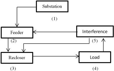
Figure 1. Research flow.
Substation is located at the Kecamatan Semampir Surabaya is a collection and retrieval of data feeders Tambak Wedi owned and server Electricity Company Network Services, Unit (UPJ) Kenjeran.
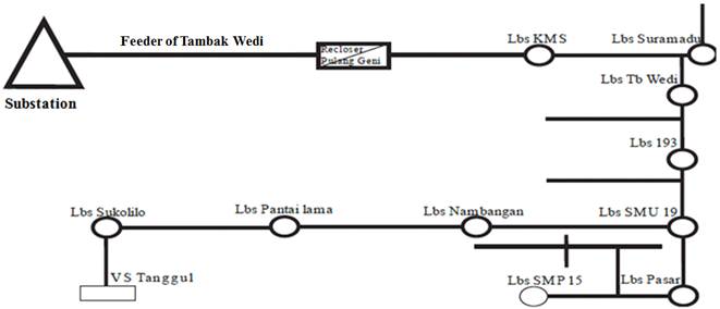
Figure 2. Feeder Tambak Wedi.
If interference occurs feeders Tambak Wedi, then Recloser Pulanggeni will detect the magnitude of the fault current and show relay that work as well as the phase of what has been disruption.
To calculate the short-circuit current in medium voltage distribution network, which is in supply of the substation 150 KV are as follows:
1. Sources Impedance
![]() (1)
(1)
Where:
Zs =sources impedance
KV² =sources of voltage 150 KV
MVA = Short circuit level Bus 150 KV Substation
2. Transformer impedance
![]() (2)
(2)
Where:
Zt = Transformer impedance
KV² = Power voltage transformer 20 kV
MVA = Power transformer
3. Feeder Impedance
Feeder impedance is determined from the type of conductor used. Great value impedance, positive sequence (Z1), negative sequence (Z2) and zero sequence (Z0) feeders for each Kilo Meter.
4. Equivalent impedance
The sequence of positive and negative
Z1eki = Z2eki = Zs (alongside 20KV) + Xt + Z1 feeder (3)
Where:
Z1eki = Z2eki = Impedance positive - negative sequence
Zs (alongside 20KV) = Sources impedance
Xt = Reactance the positive - negative sequence
Z1 feeder = Conductor impedance of the positive-negatifve sequence
For zero sequence
Counts are based on neutral grounding system of the substation Z0
Z0eki = Xt0 + 3Rn + Z0 feeder (4)
where:
Z0 eki = Zero sequence impedance
Xt0 = Zero sequence reactance
3Rn = System Grounding Substation
Z0 feeder = Zero sequence impedance Conductor
5. 3 phase current disturbance
![]() (5)
(5)
6. 2 phase current disturbance
![]()
7. 1 phase current disturbance – ground
![]()
where
If 3![]() = 3 phase current disturbance (Amp)
= 3 phase current disturbance (Amp)
If 2![]() =2 phase current disturbance (Amp)
=2 phase current disturbance (Amp)
If 1![]() =1 phase current disturbance-gorund (Amp)
=1 phase current disturbance-gorund (Amp)
V ph = Phase voltage – netral (Volt)
V ph – ph = Phases voltage (Volt)
Z1 eki = Positive sequence equivalent impedance (Ohm)
= (Z1sc + Z1T + Z1 network)
Z2 eki = Negative sequence equivalent impedance (Ohm)
= (Z2sc + Z2T + Z2 network)
Z0 eq = Zero sequence impedance (Ohm)
= (3Rn + Z0T + Z0 network)
Zf = Disturbance impedansi (Ohm)
4. Result & Discussions
Short circuit happened in Tambak Wedi feeders there are three kinds:
1. Short circuit of 3 phases
2. Short circuit 2 phases
3. Short circuit one phase to ground
Calculation of short circuit fault current is calculated based readable Recloser and assumed disturbance occurs in feeder length at 25%, 50%, 75% and 100%.
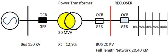
Figure 3. Various point of trouble.
4.1. The Impedance of the Source
Zs (from side 20KV)
4.2. Impedance of Transformer
Power transformer reactance value:
• Positive and negative sequence reactance (Xt1 = Xt2)
Xt1 = reactance of the transformers (%) x Zt
Xt1 = 12,9(%) x 13,3333 = 1,7199 Ω
Xt1 = Xt2 = 1,7199Ω
• Zero sequence reactance (Xt0)
Power transformer GI UJUNG have a relationship vector YNyn0 (d) which has a delta winding therein, then magnitude Xt0 = 3 Xt1.
Xt0 = 3 x 1,7199 = 5,1597 Ω
4.3. Feeder Impedance
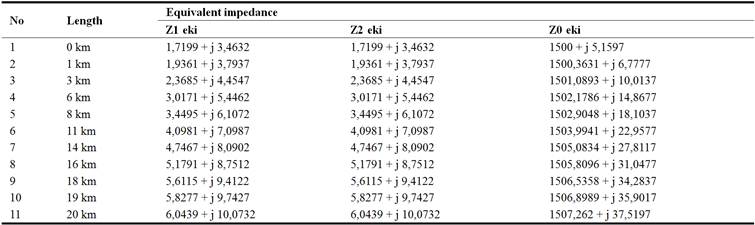
From the data obtained, feeders Tambak Wedi, using a type of conductor All Aluminum Alloy Conductor (AAAC) 150mm, with a length of feeders 20.40 Kilo Meter Circuit (KMS) thus to the fault location from a distance of 0 Kilo Meter to 20.4 Kilo Meter. Impedance values feeders for the positive sequence, negative and zero previously described.
4.4. Equivalent Impedance
Equivalent impedance calculation of positive sequence (Z1 ek) and the negative sequence (Z2ek):
Z1eki = Z2eki = Zs (from side 20KV) + Xt + Z1 feeder
Z1eki 0 km = j 3,4632 + 1,7199 + 0
= 1,7199 + j 3,4632
Calculation of the value of the equivalent impedance, zero sequence (Z0 eki):
Z0 eki = Xt0 + 3Rn + Z0 feeder
= j 5,1597 + 3 x 500 + Z0 feeder
= 1500 + j 5,1597
Table 1. Equivalent Impedance (Z1 eki, Z2 eki, Z0 eki).
A discussion of the short-circuit current
a. Three-phase short-circuit
The formula of three -phase short circuit current is
where:
I = Three-phase fault current
V = Neutral phase voltage of the system 20 KV = √ Vph
Z = Positive sequence Impedansi (Z1 eki)
Calculation of the current three-phase short circuit by using Table 1. into equation above is as follows,
In the same way the calculation of the current two-phase short circuit at the point feeder fault location Tambak Wedi can be seen in Table 2. below:
b. Short-circuit of two phases
The formula of three-phase short circuit current is
where
I = Fault current three phase
V = Phase voltage for a neutral system 20 KV = √ Vph
Z = Positip sequence impedance (Z1 eki)
Calculation of the current three-phase short circuit by using Table 1. into equation above is as follows:
In the same way to determine the calculation of the current two-phase short circuit at the point feeder fault location Tambak Wedi can be seen in Table 2. below:
c. Short circuit on single phase-ground
The formula of three -phase short circuit current is
where:
I = Three-phase fault current
V = Neutral phase voltage of the system 20 kV = √Vph
Z = Number of positip sequence impedance (Z1 eki)
= Number of positive sequence impedance (Z2 eki)
= Number of positive sequence impedance (Z0 eki)
Fault current calculations from a short circuit for the single-phase ground using Table 1 and enter into the equation above is as follows:
In the same way for the calculation of the fault current from a short circuit single-phase ground at the point of location from a disturbance feeders Tambak Wedi can be seen in Table 2. below:
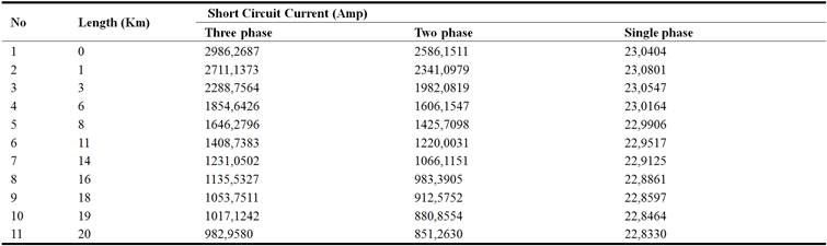
Table 2. Short-circuit three-phase, two-phase and single phase to ground.
5. Conclusion
Based on the results and the discussion it can be concluded that the current noise, a short circuit to air channels with a medium voltage (SUTM) at Tambak Wedi feeder, which has been read by Recloser is for a three-phase short circuit at 2986.27 Ampere, a two-phase short circuit at 2586.15 Ampere and single phase to ground 23.04 Ampere.
References
- Pribadi, K. 2011. Protection of the electric power system, Penerbit Garamond, Kota Depok.
- Baskara rieza. 2010. The use and maintenance of the separator (PMS) in substations of 150 KV Srondol PT PLN (Persero) P3BJB Region Jawa UPT Central and DIY Semarang Universitas Diponegoro Semarang.
- Wahyudi, sn. 2011. The second edition engineering services, Penerbit Garamond, Kota Depok.
- Sutarti. 2012. Automatic breaker on the distribution network of medium voltage 20KV, Jurnal Media elektrika vol 5 no 2.
- Sugeng Priyono. 2013. Bina Teknik, vol. 1 no. 0654 – 185x, Majalah Ilmiah Fakultas Teknik Universitas Negeri Medan.
- Irfan Affandi. 2012. The work of Recloser during disturbances feeders, Jurnal Media Elektrika, Vol. 2 no. 6, Januari.
- Dwi Puji hariyanto. 2013. Automatic protection on voltage network intermediate 20 KV, Jurnal Media Elektrika, Vol. 4, no. 6, Januari.
- Tiyono Sutarno. 2012. Planning medium -voltage wires in the plantation complex amp, Jurnal Teknik Elektro ITP, Vol. 1, no, 2, Januari.
- Lorenzo peretto, Nenad uzelac, Blair kerr, Elisa scala. 2015. High accuracy measurement capabilities integrated into reclosers for mv power networks, 23rd international conference on electricity distribution, cired, lyon, 15-18 june 2015.
- Aleksandar Pregelj, Miroslav Begovic, and Ajeet Rohatgi,. 2006. Recloser Allocation for Improved Reliability of DG-Enhanced Distribution Networks, IEEE transactions on power systems, vol. 21, no. 3, August 2006.
- Mohsen S. 2012. Enhancing reliability in passive anti-islanding protection schemes for distribution systems with distributed generation, Master Thesis, The University of Western Ontari.


