
Journal of Earth and Atmospheric Sciences, Vol. 1, No. 1, September 2016 Publish Date: Jul. 21, 2016 Pages: 10-21
Structural Control on Mineral Vein Geometry in the Igarra Schist Belt, Southwestern Nigeria
Efosa Udinmwen1, *, Michael Ikpi Oden1, Rufai Ayuba2, Asinya Enah Asinya1
1Department of Geology, University of Calabar, Calabar, Nigeria
2Department of Earth Science, Kogi State University, Anyigba, Nigeria
Abstract
The Igarra schist belt in the southwestern basement complex of Nigeria is part of the 3000 Km long Trans – Saharan belt. It contains Pre – Cambrian rocks with fractures and foliations commonly filled with aplite and quartz. Foliation planes in the Igarra schist belt are basically oriented in the N – S and NW – SE directions with moderate – high dip angles while the fractures dips steeply but have a more complex orientation with a dominant E – W and N – S trend. The mineral veins within the schist belt have a somewhat consistent orientation and like the structures, dip moderately/steeply. The similarities of attitudes of the veins and the structures (fracture and foliation) suggest that these structures are conduits for mineralizing fluids. The thickness and orientation of aplite and quartz veins suggest that mineralization in this schist belt was not a random process. These veins are often a few centimeters wide however the widest veins that grew to widths in excess of one meter (> 1 m) are parallel to the E – W direction. Analysis of 174 veins from metasediments and granites in the Igarra schist belt show that fracture – filling mineralizations are dominant and widest in this area. Fractures constitute the main plane of weakness in this area and they are usually parallel to the E – W direction which seems to be favoured for wide vein formation. This knowledge should guide researchers carrying out exploration for minerals in the region.
Keywords
Fracture, Foliation, Mineral Veins, Igarra, Quartz
Received: June 18, 2016
Accepted: June 30, 2016
Published online: July 21, 2016
@ 2016 The Authors. Published by American Institute of Science. This Open Access article is under the CC BY license. http://creativecommons.org/licenses/by/4.0/
1. Introduction
Mineral veins are planar – sub planar discontinuities in the Earth’s crust containing minerals precipitated from a supersaturated fluid in a fracture [1-3]. Veins form under various conditions and their widths also vary widely [4]. Vein microstructures comprise a wide range of crystal habits from dendrites, fibres, elongate-blocky to blocky crystals, depending on the boundary conditions of the crystal growth [5]. The growth of minerals in confined environments occurs in many places in the Earth's crust, from veins in the metamorphic domains to pore space in sedimentary rocks [6]. The knowledge of mineral vein geometry is fundamental to the understanding of fluid transport and depositional processes and also of significant importance during the evaluation and exploitation of mineralization [7]. Syntectonic fibres grow along the opening trajectory of fracture walls with the transport mechanism being diffusion in the dilatational site [8]. Mineral veins in ‘ac’ extension fractures are expected to trend normal to σ3 and mineral grains are expected to trend normal to the walls of fractures as grains growing normal to σ1 tend to grow fastest [9].
Theoretically, extension veins should be parallel to the applied maximum compressive stress however such extensional veins in conjugate sets either converge or diverge from the maximum principal stress [10]. In a tectonic region, mineral veins could grow by the crack-seal mechanism and it is the fractures oriented parallel to the σ1 direction (extension fractures) that is most likely mineralized [11,12]. These extension fractures will progressively open to accommodate extensional strain so that veins can form whereas other fractures (shear fractures) will mainly show slip along their surfaces and develop into faults [13]. Thus in a natural setting, one would expect that only one set of veins would develop out of extension fractures however when different sets of veins exists, the veins parallel to the maximum compressive stress direction usually grow widest [14]. This is because fractures normal or sub-parallel to the σ3 direction would try to grow grains parallel to the σ1 direction which would strongly impede their growth [11].
The formation of hydrothermal mineral deposits is basically due to the association between processes such as structural (deformation and development of favourable structures), hydrological (fluid flow), thermal (geothermal transport) and geochemical (mineral dissolution and precipitation) processes [15]. In various geological setting and different regions of the world, structural processes represent one type of critical control on mineralization [16]. On a regional tectonic scale, studies have shown that structures play a major role in the localization of mineral deposits such as gold deposits in accretional orogenic belts at subduction plate margins [17] and copper deposits associated with compressive continental crust in association with magmatism, uplift and erosion [18,19].
Structural controls on mineral deposits and vein geometry have been documented from different regions of the world. Examples are the the copper – silver deposits of D. R. Congo [20], the barite mineralization in the Ikom – Mamfe basin and the Benue Trough of Nigeria which are emplaced mainly extension fractures [21,14], the gold mineralization localized in northeast trending, steeply northwest dipping vein systems in Elizabeth, British Columbia [22], the gold – quartz vein deposits at Donalda, Albitibi greenstone belt, Canada which are perpendicular to sub – vertical shear zones [23], the calcite deposits emplaced in extension and shear fractures in the Bristol Channel basin, UK [10].
Analyzing structural factors controlling mineralization in an area can lead to the determination of exploration targets and the discovery of ore bodies [24,25]. Thus the structure and mineral vein geometry in the Igarra schist belt is studied. Considering the fact that this schist belt is probably the most expose schist belt in the Nigerian basement complex hosting different variety of rock types which allows the observation of vein geometry irrespective of the physical properties of the host rock, the Igarra schist belt is most suited for this study. Also the Igarra schist belt, just like other Pan – African schist belt was deformed by the Pan – African orogeny thus this research is a preliminary study for the structure control on mineralizations in Pan – African domains.
2. Geologic Setting
The Igarra schist belt is one of over thirteen schist belts in the Nigerian Pan – African domain and runs it for many kilometers in an approximately N-S/NNW-SSE direction. This belt has been studied by [26] and it contains the Igarra Formation which runs for about 60km in the general NNW-SSE direction and occupies an area of over 750km2, bounded to the north by the Kabba-Jakura Formation. The Igarra area is 60% exposed in some parts [27] and has been mapped to varying degrees by [27–30]. Recent studies [31,32] have affirmed the older works which revealed that the main group of rocks in this area are the migmatite-gneiss complex, the metasediments composed of metaconglomerates, quartzites, calc-gneisses and schists, the syn – tectonic Older Granites and the late discordant non-metamorphosed syenite dyke.
The migmatite-gneiss complex can be divided into mappable units only with considerable difficulty [26]. Such difficulties are apparently due to obscuring effects of migmatization and metasomatism. The effects of these processes on rocks of varying composition tend to result in a convergence toward a granite or granodioritic composition [26]. The study area is within the southern region of the Igarra schist belt of the southwestern basement complex of Nigeria which lies to the east of the West African craton, north of the Borborema province and south of the Adrar des Iforas and Hoggar in the region of Late Precambrian to early Palaeozoic Orogenesis (Fig. 1). This area lies within the Igarra town and its environs (Fig. 2) and forms the down-left quadrant of the Lokoja sheet 62 produced by the Geological Survey of Nigeria. Its topography is undulating with elevation reaching 500m at the granite peaks [33] and it lies within the tropical rain forest belt of Nigeria.
3. Methodology
This study involves the detailed mapping of rocks and structures with particular interest in the mineral vein behavior with respect to other structures. The field mapping was carried out in three phases between June 2012 and August 2013 and a data confirmation reconnaissance mapping was done in December 2014. Detailed mapping of the Igarra schist belt was done on a topographic map with a scale of 1:25,000 covering an area of over 850 Km2. The map was sub divided into 12 grids with the northern 9 grids covering an area of about 85.5 Km2 each and the lower 3 grids covering an area of about 34.2 Km2. The geology and structures each grid was mapped systematically and a geologic map with few structural features of the schist belt was produced and digitized using ArcGIS 10 software (Fig. 2). The major equipment’s used for this study includes a Garmin 76 Global Positioning System (GPS), Silva Compass Clinometer and a measuring tape. The attitude of structures which hosts mineral veins (joints and foliations) were measured using standard structural techniques and presented using stereographic projection and rose diagram. The attitude and width of mineral veins was also measured and this information was used to prepare a scatter plot of vein width versus orientation.
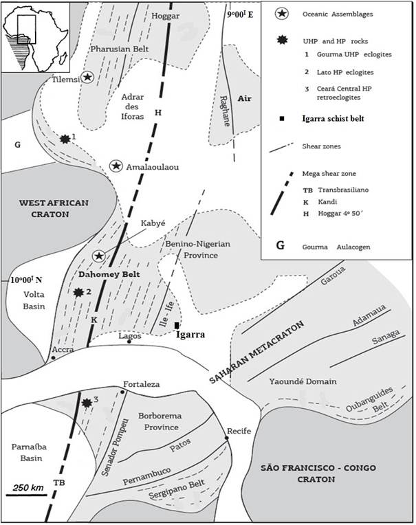
Fig. 1. Regional geologic correlation of north eastern south America and north western Africa showing the Neoproterozoic (Pan – African) regions of Nigeria in West Africa. Modified from [34].
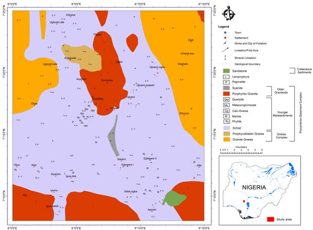
Fig. 2. Geological map of the study area.
4. Results
4.1. Joint Analysis
Joints are usually the most common secondary structures exposed on the present day surfaces of rocks and though they may seem featureless, they constitute a vital structural element both regionally and locally as they can elucidate the tectonic history of a region if properly studied [10,13,35]. All the rocks in the Igarra area are jointed to varying degrees (Fig. 3 a – d).
The joints are usually straight (Fig. 3a) on the surface but are sometimes curved, with smooth planar surfaces (Fig. 3c). Along the Igarra – Ibillo express way, a series of well developed; steeply dipping joints are observed in a granite dyke west of Igarra (Fig. 3b). The gneisses (Fig. 3c) are also characterized by such steep joints while the schist has joints which cut normal to the foliation surface. T – Intersection joint patterns (Fig. 3d) are regularly observed in the granites with the joint labeled x trending E-W while that labeled y is trending N-S. Joint y (N – S) terminates at joint x (E-W) and such situation shows that the joint terminating against another joint is younger than it [36]. Fig. 4 shows the stereographic projections of poles to planes of joints from different rocks in the Igarra area which have been contoured using the Fisher distribution counting method. Stereographic analysis of joints from gneisses shows that the joints are high angle E-W trending structures (Fig. 4a).
However the same is not true of the granites which show two joint sets which are a major, high angle, E-W trending set and a minor medium angle N-S trending set commonly found along Igarra – Ibillo express way (Fig. 4b). The quartzite and schist show dominant high angle E-W trending joints (Fig. 4 c and d), although the schist have a minor N-S set (Fig. 4 d). The gneiss displays a strong E – W trending joint set with a very weak NE – SW set (Fig. 4 a), the granites have a strong E – W and N – S sets and a weaker low angle NW – SE set (Fig. 4 b), while joints in the schist and quartzite are all strongly oriented in the E – W direction (Figs. 4 c and d), however the N – S joints are weakly occurring in the schist (Figs. 4 c) and they also recorded a very weak NE – SW joint set (Fig. 4 c). Generally, jointing in the study area (Fig. 5) shows two major sets which are the much more dominant E-W trending fractures and the less frequently occurring N-S trending joints. The joints are usually high to medium angle with no preferred direction of dip.
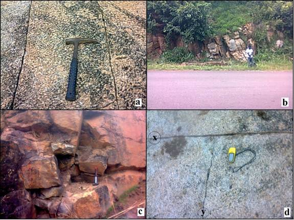
Fig. 3. Joints in the study area (a) Parallel E-W joints at Enwan (b) Series of N-S trending joints along Igarra – Ibillo express way (c) Steeply inclined joints in gneiss (d) T – joints in granite showing their age relationship.
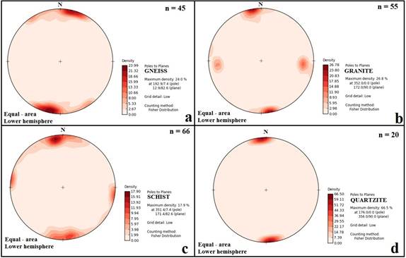
Fig. 4. Lower Hemisphere Stereographic projections of joints as poles (a) Stereographic projection of joints in gneiss (b) Stereographic projection of joints in granite (c) Stereographic projection of joints in schist (d) Stereographic projection of joints in quartzite.
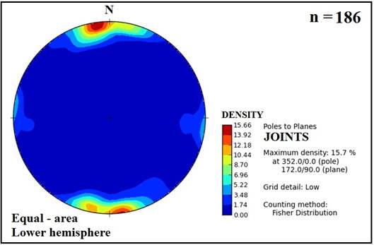
Fig. 5. Combined stereographic projection of the poles to joint planes in the rocks of the study area.
4.2. Foliation Analysis
Foliation is a general term for a planar arrangement of small-scale textural, crystallographic and/or structural features - a "planar fabric" - in any type of rock [37]. It has been applied, for example, to cleavage in slates, to schistosity or gneissic structure in metamorphic rocks, to flow structure in granites, to ice fabrics in glaciers, and even to fabrics of sedimentary origin [38]. However, the term used alone is mainly applied to planar fabrics in deformed and metamorphosed crystalline rocks (metamorphic tectonites), although "tectonic foliation" or "secondary foliation" would be more appropriate terms. The foliated rocks in this study are schist, gneiss, and quartzite. The foliation planes in the schist may be massive showing very poor cleavage (Fig. 6 a), while others are vertical or near vertical (Fig. 6b).
The gneisses are strongly foliated in the N-S direction however, a very minor E-W oriented foliation planes were observed (Fig. 7 a). The dip of the gneissose foliation ranges from very low to medium angle (Fig. 7 b). The schist foliation planes are preferentially oriented in the NW - SE and N - S directions with high to medium dip angles (Fig. 7 c and d). The quartzite foliations are strictly oriented in the NW - SE direction with medium angle dips between 30° and 70° (Fig. 7 e and f). Generally, the foliation planes of metamorphic rocks in the area have two preferred directions which are the N - S and NW - SE directions, their dips being mostly medium to high angle.
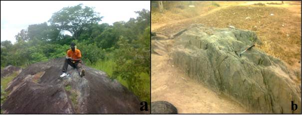
Fig. 6. Features of foliation planes in the study area (a) Foliation plane showing poor fissility (b) Vertical foliation in schist.
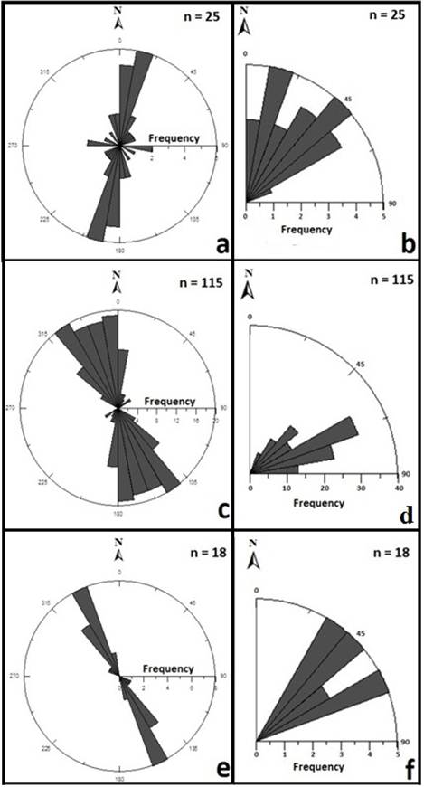
Fig. 7. Rose and dip diagrams of foliation planes in the study area (a) Rose diagram of foliation planes measured from gneisses (b) Dip diagram of foliation planes measured from gneisses (c) Rose diagram of foliation planes measured from schists (d) Dip diagram of foliation planes measured from schists (e) Rose diagram of foliation planes measured from quartzites (f) Dip diagram of foliation planes measured from quartzites.
4.3. Mineral Vein Analysis
The mineral veins in the study area were emplaced in all available planes of weakness (Fig. 8). The veins emplaced in fractures have high angle dips while those occupying foliation planes possess moderate dips. The wider veins are basically pegmatite (Fig. 8 a and b). The E-W trending veins in the granites are usually wider and in some cases contain a length parallel crack (Fig. 8 c) as though a crack-seal process was being initiated. On the other hand the N-S trending veins are very thin to the order of few centimeters (Fig. 8 d) and these thin veins are usually quartz. In the quartzite’s, the mineral veins were emplaced in joints oblique to the foliation planes (Fig. 8 e) as well as along the foliations themselves (Fig. 8 f). The orientation of the mineral veins in the gneisses is parallel to the N-S direction though minor trends like E-W and NE-SW veins also occur (Fig. 9 a). Veins in the schist were dominantly emplaced in the NE-SW and NW-SE directions however; minor trends are observed in the E-W direction (Fig. 9 b). The dominant orientation of mineral veins in the granites is in the E-W direction; however, the N-S oriented veins appreciably register their presence in the granites (Fig. 9 c). Generally, mineral veins in the rocks of the Igarra area are oriented along two major directions (E-W and N-S) and two minor directions (NW-SE and NE-SW) (Fig. 9 d). While the E-W trending veins are more dominant, the NW-SE veins occur more than the NE-SW trending veins.
The formation of mineral veins at high fluid pressure and low metamorphic temperature or grade is usually associated with crack – seal structures [2,39], and the growth of these veins usually involves a process of repeated small increments, the crack – seal mechanism [39]. The crack – seal process correspond to repeated successive parallel fractures that are believed to have propagated by a subcritical cracking process in the presence of mineralizing fluids [40]. [41] stated that the crack – seal process involves the initiation and propagation of a crack in the rock due to the buildup of elastic strain in the rock and the release of this deformation by a fracture process. After fracturing, there is loss of cohesion in the rock (Fig. 10) and the crack separate slightly before fluids can invade the crack to form a new crystalline material deposited on the walls of the crack to re – establish cohesion in the crack (Fig. 10). Once the walls of the crack are sealed, tectonic stresses have continuity through the vein and can build up again until a critical failure stress is reached [41]. Due to the planar anisotropy introduced by the initial vein, it is common for the first vein to control the location of other veins. The new vein often forms inside the earlier one, by splitting into two parts or forming along the vein to wall contact (Fig. 10). The process of sealing now continues until there is wall to wall cohesion between the separations induced by the new crack and this cycle is repeated, often leading to the formation of wide veins made up of composite microveins.
Veins attributed to the crack – seal mechanism are commonly considered as evidence of episodic crack opening, driven by oscillations in fluid pressure or bulk stress [42]. Indicators of the crack – seal process are regularly spaced band of small inclusions aligned parallel to the vein walls and the opening per crack event is generally in the order of several micrometers to tens of several micrometers [40,43]. The mineral veins in the Southern Igarra schist belt is mostly pegmatite, quartz and in some cases aplite. A graph of the orientation of the mineral veins against their widths (Fig. 11) shows that the veins oriented parallel to the E-W direction conspicuously grew wider than veins in all other directions. The crack – seal mechanism increases the width of mineral vein.
Although there is no clear cut evidence supporting the occurrence of the crack seal process in this region, some of the E – W veins contain length parallel crack as though a crack – seal process was being initiated.
5. Discussion
The mineral vein pattern and the possible structures which can control the geometry of these veins have been analysed in this study. In this area, the rocks which bear meaningful veins are granites, gneisses, schists and quartzites. In the granite, it is quite evident that the joints controlled the geometry of the veins. The joints in the granites have two basic trends which are parallel to the E – W and N – S, similarly the mineral veins are also oriented in the E – W and N – S directions. The mineral veins in the granite parallel to the E – W direction are much larger than those in the N – S direction (Fig 10) which indicates a preference for vein growth in the E – W direction. In the granite of this region, the E – W and N – S fractures have been identified as "ac" extension and "bc" tensile fractures respectively [11,32,44] and it is well documented that mineral growth is favoured by the "ac" extension fractures parallel to σ1 direction [10, 12–14, 21]. In the schists, the mineral veins are mostly oriented in the NW – SE, E – W and NE – SW directions. The NW – SE veins were obviously emplaced along foliation planes while the E – W vein geometry is controlled by fractures. In the gneisses, the mineral veins are basically in the N – S, NE – SW and a few E – W veins. The N – S and few E – W veins in the gneisses are controlled by "bc" tensile and "ac" extension fractures respectively.
Interestingly, the few E – W trending mineral veins in the gneisses are well larger and wider than the dominant N – S veins (Fig. 11). This again indicates that the growth of mineral veins in this area favoured the E – W direction in this area. The quartzite basically loaded veins along the foliation planes and along fractures which are normal or oblique to the foliation. This phenomenon is often easily observed in the field (Fig. 11). Mineral veins are often loaded in "ac" extension fractures parallel to σ1 direction. Considering all the mineral veins in the study area, the preference for larger and wider veins in the E – W direction is quite consistent irrespective of rock type and such consistency in mineral vein geometry as is observed in this region is probably a safe diagnostic criterion to identify the "ac" extension fractures and can indirectly suggest the direction of maximum compression. The growth of mineral veins is sometimes enhanced by the crack – seal process [41] as shown in Fig. 10. Although no hard evidence of this process was identified in the study area, some mineral veins especially in the granites contains length parallel cracks ass though a crack – seal process was been initiated. This study has shown that the most prospective mineral veins are oriented in the E – W direction and this knowledge should guide those carrying out geophysical traverses and other surface exploration activities for minerals.
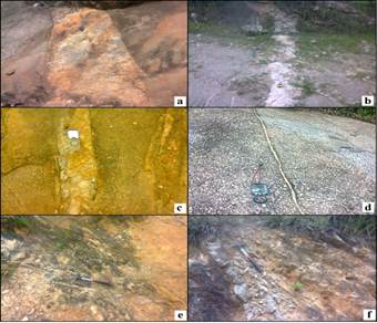
Fig. 8. Mineral veins in fractures and foliations in the study area (a) Pegmatite vein in granite (b) pegmatite dyke in gneiss (c) Quartz vein in granite showing a length parallel crack (d) Thin quartz vein in granite (e) Quartz vein in quartzite emplaced in fractures oblique to the foliation (f) Quartz vein in quartzite emplaced along the foliation.
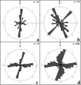
Fig. 9. Plots of mineral vein orientations of pegmatite and quartz (a) Rose diagram of veins in gneiss (b) Rose diagram of veins in schist (c) Rose diagram of veins in granite (d) Rose diagram of all mineral veins measured from the Igarra area.
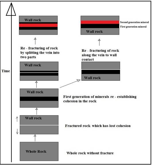
Fig. 10. Schematic sketch of the process of crack – seal mechanism.
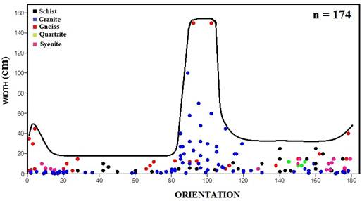
Fig. 11. Graph of width against orientation of mineral veins in the study area.
6. Conclusion
The southern Igarra schist belt contains numerous mineral veins mostly pegmatite and quartz veins. The presence of mineral veins in variable orientation in different rock types is an indication that mineralized hydrothermal fluids invaded all available opening in the area. The similarity of mineral vein geometry with the attitude of joints and foliation shows that these structures were conduits for mineralizing fluids. In the area, the mineral veins oriented parallel to the E – W direction grew wider and larger in all the rock type irrespective of their availability and this consistency is probably a safe diagnostic criterion to identify the "ac" extension fractures and can indirectly suggest the direction of maximum compression. The most prospective mineral veins are oriented in the E – W direction and this knowledge should guide those carrying out geophysical traverses and other surface exploration activities for minerals.
References
- Urai, T. L., Williams, P. F and Van Roermond, H. L. M., 1991. Kinematics of crystal growth in syntectonic fibrous veins. Journal of structural Geology. 13, 823–836.
- Hubert, J., Emmerich, H and Urai, J. L., 2009. Modelling the evolution of vein microstructure with phase – field technique – a first look. Journal of Metamorphic Geology, 27, 523–530.
- Ankit, K., Nestler, B., Selzer, M and Reichardt, M., 2013. Phase-field study of grain boundary tracking behavior in crack-seal microstructures. Contributions to Mineralogy and Petrology, 1–26.
- Oliver, N. H. S and Bons, P. D., 2001. Mechanisms of fluid flow and fluid – rock interaction in fossil metamorphic hydrothermal system inferred from vein – wall rock patters, geometry and microstructure. Geofluids, 1 (2), 137.
- Ankit, K., Pilipenko, D., Kundin, J and Emmerich, H., 2011. Modelling mineral vein dynamics - a phase field approach. Geophysical Research Abstracts. 13, EGU2011-12193.
- Noiriel, C., Renard, F., Doan, M – L and Gratier, J – P., 2010 Intense fracturing and fracture sealing induced by mineral growth in porous rocks. Chemical Geology 269, 197–209.
- Dominy, S.C and Camm, G.S., 1997.Controls on ore localization in tin-bearing veins: a review.Annual Conference of the Ussher Society, 241–249.
- Durney, D and Ramsay, J. G., 1973. Incremental strains measured by syntectoniccrystal growth. Gravity and Tectonics, Wiley, New York.
- Kamb, W. B., 1959. Theory of preferred crystal orientation develop by crystallization under stress. Journal of Geology, 67: 153-170.
- Belayneh, M and Cosgrove, J.W., 2010. Hybrid veins from the southern margin of the Bristol Channel Basin, UK. Journal of Structural Geology. 32,192–201.
- Oden, M. I. and Udinmwen, E., 2014a. Fracture characterization, mineral vein evolution and the tectonic pattern of Igarra syn- tectonic granite, southwestern Nigeria. British Journal of Applied Science and Technology. 4(17), 2417–2429.
- Oden, M. I., Umagu, C. I and Udinmwen, E., 2016. The use of jointing to infer deformation episodes and relative ages of minor Cretaceous intrusives in the western part of Ikom – Mamfe basin, southeastern Nigeria. Journal of African Earth Science. DOI:10.1016/j.jafrearsci.2016.02.010.
- Koehn, D., Arnold, J and Passchier, C. W., 2005. Fracture and vein patterns as indicators of deformation histories: a numerical study. Geological Society of London, Special Publications, 243, 11–24.
- Oden, M. I., 2012. Barite veins in the Benue Trough: Field characteristics, the quality Issue and some tectonic implications. Environment and Natural Resources Research, 2(2), 21–31.
- Zhang, Y., Schaubs, P. M., Zhao, C., Ord, A., Hobbs, B.E and Barnicoat, A., 2008. Fault-related dilation, permeability enhancement, fluid flow and mineral precipitation patterns: numerical models. In: C. A. Wibberley, W. Kurz, J. Imber, R.E. Holdsworth, C. Collettini (Eds.) The Internal Structure of Fault Zones: Implications for Mechanical and Fluid-Flow Properties, Geological Society, London, Special Publications, 299, 239–255.
- Zhang, Y., Robinson, J and Schaubs, P. M., 2011.Numerical modeling of structural controls on fluid flow and mineralization.Geoscience Frontiers, 2 (3), 449–461.
- Goldfarb, R. J., Groves, D. I and Gardoll, S., 2001. Orogenic gold and geologic time: a global synthesis. Ore Geology Reviews, 18, 1–75.
- Cooke, D. R., Hollings, P and Walshe, J. L., 2005. Giant porphyry deposits: characteristics, distribution, and tectonic controls. Economic Geology, 100, 801–818.
- Hollings, P., Cooke, D and Clark, A., 2005. Regional geochemistry of tertiary igneous rocks in central Chile: implications for the geodynamic environment of giant porphyry copper and epithermal gold mineralization. Economic Geology, 100, 887–904.
- Haest, M., Muchez, P., Dewaele, S., Franey, N and Tyler, R., 2007. Structural control on the Dikulushi Cu–Ag deposit, Katanga, Democratic Republic of Congo. Economic Geology, 102, 1321–1333.
- Oden, M. I., Egeh, E. U and Amah, E. A., 2015. The Ikom – Mamfe basin Nigeria: A study of fracture and mineral vein lineament trends and Cretaceous deformations. Journal of African Earth Sciences. 101; 35–41.
- Siddorn, J and Lee, C., 2005. Structural geology of the Elizabeth gold project, British Columbia. SRK Consulting, SRK 2CJ003.002.
- Chi, G and Guha, J., 2011.Microstructural analysis of a subhorizontal gold-quartz vein deposit at Donalda, Abitibi greenstone belt, Canada: Implications for hydrodynamic regime and fluid-structural relationship. Geoscience Frontiers. 2(4), 529–538.
- Dugdale, L. J., 2009. Adding value to exploration—Reducing time and cost to discovery in Western Victoria. Geoscience Australia Record, 9, 39–44.
- Liu, L. M., Zhao, Y. L and Zhao, C., 2010. Coupled geodynamics in the formation of Cu skarn deposits in the Tongling-Anqing district, China: computational modeling and implications for exploration. Journal of Geochemical Exploration, 106, 146–155.
- Hockey, R. D., Sacchi, R., Muotoh, E. O. G and Graaff, W. P. F. H., 1986. The Geology of Lokoja-Auchi Area. Geol. Sury. Nig. Bul. 39. 71.
- Egbuniwe, I. G and Ocan, O. O., 2009. Selection of fieldwork area for teaching/training: Igarra Area as an example. In: Proceedings of field mapping standardization workshop. D.O Lambert-Aikhionbare and A.I Olayinka (Eds).University of Ibadan press. 79–95.
- Odeyemi, I. B., 1976. Preliminary report in the relationships of the Basement complex rocks around Igarra, Mid-west. In: Geology of Nigeria, edited by C. A Kogbe. Elizabethan Publ. Lagos. 59-63.
- Odeyemi, I. B. and Rahaman M. A., 1992. The petrology of a composite syenite dyke in Igarra, southwestern Nigeria. Journal of Mining and Geology. 28 (2), 255-263.
- Okeke, P. O., Akinnagbe, T. and Anike, L. O., 1988. Major and minor element evaluation of the Igarra granite. Journal of Mining and Geology. 24 (1) 101-106.
- Adepoju, M. O and Adekoya, J. A., 2011. Reconnaissance geochemical study of a part of Igarra schist belt, southwestern Nigeria. Ife Journal of Science. 13 (1), 75–92.
- Oden, M. I. and Udinmwen, E., 2014b. Mesoscopic structural profile of a syn – tectonic granite, southwesern Nigeria. IOSR Journal of Applied Geology and Geophysics. 2(2), 67–76.
- Oden, M. I. and Udinmwen, E., 2013. The behaviour of K-feldspar phenocrysts and strain anisotropy in Igarra syn-tectonic granite, southwestern, Nigeria. Current Advances in Environmental Science, 1(2), 9-15.
- Cordiani, U.G., Pimentel, M.M., De Araujo, C.E.G., Basei, M.A.S., Fuck, R.A and Girardi, V.A.V., 2014. Reply to comment by E. Tohever and R. Trindade on "Was there a Clymene ocean in central south America?". American Journal of Science, 3114, 814–819.
- Engelder, T. and Geiser, P., 1980. On the use of regional joint sets as trajectories of paleostress fields during the development of the Appalachian plateau, New York. J. Geophys. Res., 85(11), 6319-6341.
- Davis, G. H and Reynolds, S. J. (1996). Structural Geology of Rocks and Regions. John Wiley and sons. 371p.
- Milnes, A. G., Hudson, J., Wikström, L and Aaltonen, I., 2006. Foliation: geological background, rock mechanics significance, and preliminary investigations at Olkiluoto. Posiva Working Report, 2006–03.
- Passchier, C.W and Trouw, R.A.J., 1996. Microtectonics. Springer, Berlin.
- Becker, S., Hilgers, C., Kukla, P.A and Urai, J.L., 2011. Crack-seal microstructure evolution in bi- mineralic quartz – chlorite veins in shales and siltstones from the RWTH-1 well, Aachen, Germany. Journal of Structural Geology, 33, 676–689.
- Renard, F., Andreani, M., Boullier, A and Labaume, P., 2004. Crack – seal patterns: records of uncorrelated stress release variations in crustal rocks. In: D. Gapais, J. P Brun, and P. R Cobbold (Eds). Deformation mechanism, rheology and tectonics: from mineral to lithosphere. Geological Society of London Publication, 81–94.
- Ramsay, J. G. and Huber, M. I. (1987). The Techniques of Modern Structural Geology, Vol 2. Folds and Fractures. Academic Press London. 700p.
- Petit, J. P., Wibberley, C. A. J and Ruiz, G., 1999. "Crack – Seal" slip: a new fault valve mechanism? Journal of Structural Geology. 21, 1199–1207.
- Xu, G., 1997. Fluid inclusions in crack – seal veins at Dugald River, Mount Isa Inlier: implication for palaeostress states and deformation condition during orogenesis. Journal of Structural Geology. 19, 1359–1368.
- Udinmwen, E., 2016. Strain analysis and structural evolution of the Precambrian rocks of southern Igarra schist belt, southwestern Nigeria. M.Sc Thesis, University of Calabar, Nigeria. 168p.


