
Chemistry Journal, Vol. 1, No. 3, June 2015 Publish Date: Apr. 22, 2015 Pages: 81-89
Thermochemical Boriding of Iron–Chromium Alloys
V. I. Dybkov*
Institute of Problems of Materials Science, National Academy of Sciences of Ukraine, Kyiv, Ukraine
Abstract
Thermochemical boriding of iron–chromium alloy (5, 15 and 30%Cr) samples in boron powder at 850–950ºC and reaction times 3600-43200 s leads to the formation on their surface of two boride layers. In the case of 5 and 15% Cr alloys, the outer layer bordering boron consists of the FeB compound, while the inner adjacent to the alloy base consists of the Fe2B compound. Each boride layer is a homogeneous phase (microstructure of the first kind). With a 30% Cr alloy, the outer layer comprises the FeB and CrB compounds, while the inner comprises the Fe2B and Cr2B compounds. Each boride layer is two-phase (microstructure of the second kind). In the case of a 5% Cr alloy, the FeB and Fe2B layers occur sequentially, with the Fe2B layer being the first to form and grow. The continuous FeB layer is only formed if the thickness of the Fe2B layer exceeds, depending on the temperature of reaction, 100–180µm. With 15 and 30% Cr alloys, a reaction time of 3600 s is sufficient for both the FeB and Fe2B layers to occur. The characteristic feature of the layers is a profound texture. Their growth rate obeys a parabolic relation. Boride layers with the microstructure of the second kind exhibit a higher dry abrasive wear resistance than those with the microstructure of the first kind.
Keywords
Iron-Chromium Alloys, Boride Layers, Structure, Chemical Composition, Mechanism of Formation, Growth Kinetics, Dry Abrasive Wear Resistance
Received: March 27, 2015
Accepted: Apri1 2, 2015
Published online: April 20, 2015
@ 2015 The Authors. Published by American Institute of Science. This Open Access article is under the CCBY-NC license. http://creativecommons.org/licenses/by-nc/4.0/
Contents
1. Introduction 2. Experimental 2.1. Materials and Samples 2.2. Investigational Methods 3. Results and Discussion 3.1. Constituent Phases and Chemical Composition of Boride Layers 3.2. Sequence and Mechanism of Formation of Boride Layers 3.3. Growth Kinetics of Boride Layers 3.4. Microhardness of Boride Phases 3.5. Dry Abrasive Wear Resistance of Boride Layers 4. Conclusions Acknowledgments
1. Introduction
Thermochemical surface boriding is often employed to enhance service properties of metals, alloys and steels [1-3]. It ensures a high increase in resistance of original parts or products to abrasion, mechanical and corrosive wear. Examples of practical applications of borided parts include agricultural machinery and aerospace components, automobile and tractor gears, pipe fittings, high wear pumps, tools and dies, steam turbine blades and many others. Such parts usually serve two to five times longer than those treated with conventional techniques such as hardening, carburizing, nitriding or nitrocarburizing. If necessary, all these may readily be combined to obtain a surface coating of desirable chemical, physical and mechanical properties.
In this work, experimental data on thermochemical boriding of iron–chromium alloys containing 5, 15 and 30% Cr in a mixture of amorphous boron powder and KBF4 (activator) at 850-950ºC are presented, with the main emphasis on establishing the structure, chemical composition, mechanism of formation, growth kinetics and dry abrasive wear resistance of boride layers formed on the alloy surface. These high chromium alloys were chosen for the investigation because the studies of previous researchers (see, for example, [4-11]) were carried out largely with low alloyed steels containing 4% Cr or less. This chromium content appeared to be insufficient to reveal a few essential features (notably, different kinds of microstructure and different chemical composition) typical of boride layers formed on the surface of alloy samples with its much higher contents.
2. Experimental
2.1. Materials and Samples
Initial alloys in the form of rods, 13 mm diameter, were prepared by arc-melting from carbonyl iron powder (99.98% Fe) and electrolytic-grade chromium platelets (99.98%Cr). Reagents were amorphous boron (98.3% B) and analytical-grade KBF4. All contents are given in mass percent if otherwise not stated.
Tablet samples, 11.28mm diameter (1.0 cm2area) and 5.5 mm high, were machined from alloy rods obtained. Their flat sides were ground and polished mechanically.
2.2. Investigational Methods
The vacuum device VPBD-2S employed for thermochemical boriding of alloy samples and its experimental cell are described elsewhere [12]. The alloy tablet was embedded into a mixture of boron powder with 5% KBF4 as an activator. This amount of KBF4 is considered to be optimum [1,13]. Experiments were carried out at a temperature of 850, 900 and 950ºC under high-purity argon (99.999vol.% Ar) at a reduced pressure of 2.5×10⁴Pa. Their duration was 3600–43200 s (1–12h). The temperature measured with a Pt–PtRh thermocouple was maintained constant within ±1ºC with the help of an automatic thermoregulator VRT-3.
After the experiment, the tablet with boride coatings was cut along the cylindrical axis into two unequal parts (4mm and 7mm) using an electric-spark machine. Its greater part was embedded into a cold-setting epoxy resin and used to prepare a metallographic cross-section. The lesser part was used for X-ray diffraction investigations (plan-view samples).
Characterization of initial alloy samples and boride layers formed on their surface was carried out with the help of metallography, X-ray diffraction (XRD) and chemical (CA) analyses, and electron probe microanalysis (EPMA). The thickness of boride layers was evaluated using the pictures obtained on an optical microscope MIM-7 equipped with a HP Photosmart 720 camera.
Micrographs (backscattered electron images – BEI), contents of boron, iron and chromium of boride phases, and concentration profiles of these elements in the transition zone between the reactants were obtained using an electron probe microanalyzer JEOL Superprobe 733. Boron, iron and chromium standards (≥99.99% each) were employed. Measurements of element contents were treated using a versatile ZAF (atomic number, absorption and fluorescence corrections) program PACM. All three elements (B, Fe and Cr) were determined simultaneously, and the composition was then normalized to 100%. Non-normalized values usually fall in the range 98-102%, providing evidence for a rather good accuracy of measurements, especially in view of the huge difference (more than two orders of magnitude) in intensity of radiation from boron and that from iron or chromium.
X-ray diffraction (XRD) patterns were taken immediately from the surface of tablet plan-view samples on a DRON-3 apparatus equipped with both a computer and a self-recording potentiometer KSP-4. Use was made of Cu Kα radiation. Before taking the first X-ray diffraction pattern, both flat surfaces of a borided tablet sample were slightly polished to smoothen available elevations around 1μm high. This practically as-received surface of the tablet was considered to be Section 0 of the sample. Then, 10 to 30 μm of a boride layer (depending upon its total thickness) was removed from the flat surface of the tablet by grinding and subsequent polishing, and another X-ray diffraction pattern was taken (Section I). This procedure was repeated at a step of 30–50 μm until the alloy base was reached. Five to eight X-ray diffraction patterns were thus taken on each borided alloy sample.
Microhardness measurements on metallographic cross-sections were carried out using a standard PMT-3 tester with the diamond pyramid (Vickers indenter). The load was 0.98N (100g).
Dry abrasive wear resistance tests of borided alloy samples were carried out in the sliding mode on P180 SiC emery paper (EP) tape (main fraction grain size 63μm, maximum 90 μm) using an AWRD-5 device. The velocity of continuous movement of the tape (25.0 m long, 0.12 m wide) was 0.35 m s–1, while the gauge length during each test was 22.0 m. The load was 50N (5.1kg). Each test was carried out along a fresh track on the tape to ensure identical conditions for all samples. The wear resistance was determined by means of weighing a sample and measuring its height before and after the test.
3. Results and Discussion
3.1. Constituent Phases and Chemical Composition of Boride Layers
With all the alloys studied, two continuous boride layers were found to form at the interface between the reactants at a temperature of 850, 900 and 950ºC (Fig.1) but not always their formation was simultaneous. In the case of 5 and 15% Cr alloys, the outer boride layer bordering boron is a solid solution (Fe,Cr)B based on the FeB compound, whereas the inner boride layer adjacent to the solid substrate is a solid solution (Fe,Cr)2B based on the Fe2B compound.
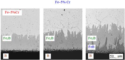
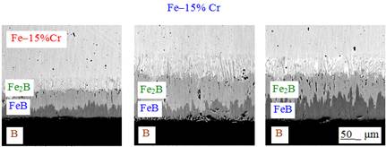
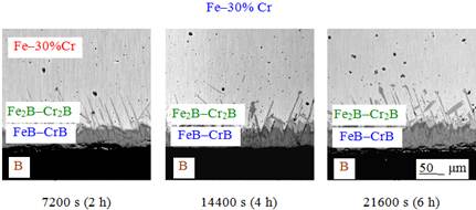
Fig. 1. Microstructure of the alloy-boron transition zone. Temperature 950ºC.
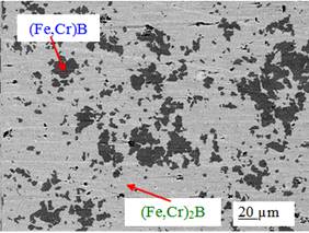
Fig. 2. Microstructure of a 5% Cr alloy sample borided at 950ºC for 21600 s in section II crossing both boride layers. The darker phase is the (Fe,Cr)B compound, while the brighter phase is the (Fe,Cr)2B compound.
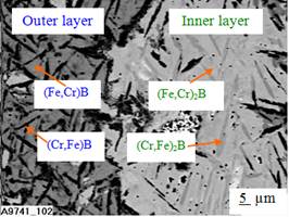
Fig. 3. Microstructure of a 30% Cr alloy sample borided at 850º C for 43200 s in section II crossing both boride layers. The dark area is the outer boride layer. Its brighter regions are the (Fe,Cr)B phase, while the darker regions are the (Cr,Fe)B phase. The bright area is the inner boride layer. Its brighter regions are the (Fe,Cr)2B phase, while the darker regions are the (Cr,Fe)2B phase.
The average chromium content is 2,7 аt.% in the (Fe,Cr)B layer and 3,5 аt.% in the (Fe,Cr)2B layer for the former alloy and 8 at.% in the FeB layer and 9 at.% in the Fe2B layer for the latter. Each boride layer is one-phase. It is a microstructure of the first kind (Fig. 2).
In contrast, both boride layers formed on the surface of 30% Cr alloy samples are two-phase (microstructure of the second kind). As seen from Fig.3 and Table1, the outer boride layer comprises the (Fe,Cr)B and (Cr,Fe)B compounds, while the inner comprises the (Fe,Cr)2B and (Cr,Fe)2B compounds. Accordingly, their chemical composition can be expressed as (Fe,Cr)B–(Cr,Fe)B and (Fe,Cr)2B–(Cr,Fe)2B.
Table 1. Average Fe, Cr and B contents of boride phases, found by EPMA measurements on borided 30% Cr alloy samples used for X-ray diffraction investigations
| Region in Fig. 3 | Content (mass%/at.%) | Compound | ||
| Fe | Cr | B | ||
| Brighter of the outer boride layer | 65.4/38.4 | 18.0/11.4 | 16.5/50.2 | (Fe,Cr)B |
| Darker of the outer boride layer | 39.8/23.5 | 44.3/28.1 | 15.9/48.4 | (Cr,Fe)B |
| Brighter of the inner boride layer | 76.9/55.7 | 14.2/11.1 | 8.9/33.2 | (Fe,Cr)2B |
| Darker of the inner boride layer | 28.1/19.7 | 62.8/47.3 | 9.1/33.0 | (Cr,Fe)2B |
With all three alloys studied, both layers possess a pronounced {002} texture and therefore consist of columnar crystals oriented preferentially in the direction of diffusion. This is considered to be a consequence of the existence of paths of enhanced diffusion in the crystal lattices of the FeB and Fe2B phases [1,7].
3.2. Sequence and Mechanism of Formation of Boride Layers
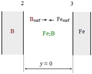
Fig. 4. Schematic diagram to illustrate the growth process of the Fe2B layer by direct chemical reaction between the surface iron and boron atoms
Figure1 provides clear evidence that in the case of a 5% Cr alloy the FeB and Fe2B layers occur sequentially, with the Fe2B layer being the first to form and grow. The continuous FeB layer is only formed after the thickness of the Fe2B layer has exceeded, depending on the temperature of reaction, 100–180µm. At 950°C, the FeB layer is seen in Fig. 1 to be missing at reaction times at least up to 14400 s. Reaction time of 3600 s in the temperature range of 850–950°C was found to be sufficient for both boride layers to form on the surface o 15 and 30% Cr alloy samples.
Initially, the Fe2B layer can readily grow at the Fe–B interface by direct chemical reaction between the surface iron and boron atoms(Fig. 4)
2Fesurf + Bsurf = Fe2B (1)
as long as these are in immediate contact with each other.
To simplify the designations and further analytical treatment of kinetic data, iron and chromium will be considered as a single chemical element (Fe). In view of the close similarity of their physico-chemical properties, this simplification does not appear to cause any misleading results.
It is clear, however, that the formation of the Fe2B layer, even one crystal-lattice thick, separates the reactants from one another, thereby making the further progress of the direct chemical reaction between the surface iron and boron atoms impossible. Subsequently, growth of the Fe2Blayer takes place at the expense of counter-diffusion of iron and boron atoms across its bulk and two further partial chemical reactions
2Fedif + Bsurf = Fe2B (21)
Bdif + 2Fesurf = Fe2B (22)
proceeding at the B–Fe2B and Fe2B–Fe interfaces, respectively, as shown in Fig. 5.
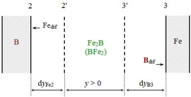
Fig. 5. Schematic diagram illustrating the growth process of the Fe2B layer by partial chemical reactions between the diffusing iron atoms and surface boron atoms at interface 2 and between the diffusing boron atoms and surface iron atoms at interface 3
These reactions cause an increase in thickness of the Fe2B layer during a time dt by dyFe2 at the former interface and by dyB3 at the latter. Note that no reaction can take place between the diffusing iron and boron atoms in the bulk of the growing Fe2B layer. Any chemical transformations (reactions) proceed entirely at the layer interfaces.
After the continuous layers of both iron borides have formed their subsequent growth under conditions of reaction (chemical) control, when the rate of diffusion of reacting atoms across their bulks exceeds the rate of interfacial transformations, is due to four partial chemical reactions (Fig. 6)
Layer Interface Reaction
![]() (31)
(31)
![]() (32)
(32)
![]() (41)
(41)
![]() (42)
(42)
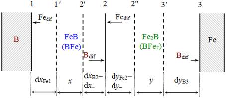
Fig. 6. Schematic diagram illustrating the growth process of the FeB and Fe2B layers under conditions of reaction (chemical) control. Arrows of different length are employed to indicate the decrease in amount of diffusing atoms, available at a particular interface, with increasing distance from an appropriate initial reactant (B or Fe)
Both components (Fe and B) are supposed to be capable of diffusing in both layers. As a result of these reactions, the thickness of the FeB layer increases during a time dt by dxFe1 at interface 1 and by dxB2 at interface 2, while that of the Fe2B layer increases during the same time by dyFe2 at interface 2 and by dyB3 at interface 3. Simultaneously, the thicknesses of the FeB and Fe2B layers decrease at their common interface 2 due to the mutual consumption in reactions (32) and (41). This decrease is dx– for the FeB layer and dy– for the Fe2B layer.
Arrows of different length are employed in Fig. 6 to indicate the decrease in amount of diffusing atoms, available at a particular interface, with increasing distance from a given reactant (boron or iron). It must be clear that only those boron atoms which have not entered into partial chemical reaction (32) at interface 2 can diffuse further to interface 3 and enter there into partial chemical reaction (42). Similarly, only those iron atoms which have not entered into partial chemical reaction (41) at interface 2 can diffuse further to interface 1 and enter there into partial chemical reaction (31).
Obviously, thickening of the FeB and Fe2B layers with passing time eventually results in a change of the regime of their growth from reaction controlled to diffusion controlled, when the rate of interfacial transformations (reactions) becomes first equal to, at a certain critical layer thickness, and then greater than, at layer thicknesses exceeding this critical value, the rate of diffusion of appropriate reacting atoms to the reaction sites (interfaces) (for more detail, see [14,15]). After the FeB layer has reached its critical thickness,![]() , with regard to boron, the Fe2B layer loses the source of boron atoms and therefore stops growing at the expense of diffusion of this component. Note that the only source of boron atoms for both layers to grow is the initial boron phase (boron powder).
, with regard to boron, the Fe2B layer loses the source of boron atoms and therefore stops growing at the expense of diffusion of this component. Note that the only source of boron atoms for both layers to grow is the initial boron phase (boron powder).
Again, after the Fe2B layer has reached its critical thickness,![]() , with regard to iron, the FeB layer loses the source of iron atoms and therefore stops growing at the expense of diffusion of this component. Clearly, the only source of iron atoms for both layers to grow is the initial iron-containing phase (Fe–Cr alloy).
, with regard to iron, the FeB layer loses the source of iron atoms and therefore stops growing at the expense of diffusion of this component. Clearly, the only source of iron atoms for both layers to grow is the initial iron-containing phase (Fe–Cr alloy).
Hence, under conditions of diffusion control the FeB and Fe2B layers are only able to grow at their common interface 2, as shown in Fig. 7. The FeB layer grows at the expense of diffusion of boron atoms across its bulk and their subsequent reaction with the Fe2B compound. The Fe2B layer grows at the expense of diffusion of iron atoms across its bulk and their subsequent reaction with the FeB compound. Thus, both boride layers grow at interface 2 by pushing each other in opposite directions.
Even though the FeB and Fe2B layers are often considered to grow entirely at the expense of diffusion of the single component boron across their bulks, it is hardly possible with compact layers having no macroscopic defects and therefore growing by the volume-diffusion mechanism. During diffusional growth, by definition, diffusion across the layer bulks is the rate-determining step, the interfacial partial chemical reactions being very fast. It means that all the boron atoms reaching interface 2 react with Fe2B to form FeB at that interface. Since under conditions of diffusion control the ability of interface 2 to combine those atoms exceeds their diffusional transport across the FeB layer, none of them can diffuse further to interface 3 and react with Fe to form Fe2B according to reaction (32): Bdif + 2Fe = Fe2B. This reaction can only take place either under conditions of reaction control when the flux of boron atoms from the initial B-containing phase is sufficient for both boride layers to grow or if the FeB layer is non-protective, due to the presence of cracks, fissures and other macroscopic defects, while boriding is carried out from a vapor or liquid phase.
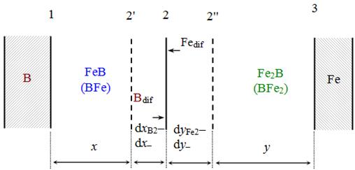
Fig. 7. Schematic diagram illustrating the growth process of the FeB and Fe2B layers under conditions of diffusion control. Both layers only thicken at their common interface 2.No partial chemical reactions can take place at interfaces 1 and 3 due to the lack of appropriate diffusing atoms (Fe at interface 1 and B at interface 3)
If boride layers are permeable to a vapor or liquid phase, direct chemical reactions between the reactants prove to be possible. Grain-boundary diffusion can also make a considerable contribution to the layer-growth process. If a few growth mechanisms are operative simultaneously, a complicated and hardly tractable microstructure of boride layers can readily be formed.
From a chemical viewpoint, it must thus be clear that the diffusionally growing compact FeB layer itself can by no means be a source of boron atoms for the Fe2B layer to grow. It only serves as a transport media for these atoms. Suppose that two FeB molecules decompose at interface2 to yield one molecule of Fe2B and one diffusing boron atom: 2FeB = Fe2B + Bdif. However, this boron atom will be unable to diffuse from interface 2 to interface 3 because under conditions of diffusion control the Fe2B surface is undersaturated with boron atoms and therefore the just-released atom is immediately combined at interface 2 according to the reaction Bdif +Fe2B = 2FeB. The net result of those reactions is zero.
In contrast, under conditions of reaction control the Fe2B surface bordering the FeB layer is oversaturated with boron atoms and therefore part of them (not combined into the FeB phase at interface 2) can readily diffuse further to interface 3 and react with the iron atoms to form Fe2B. As the source of boron atoms for both layers to grow is the boriding phase (boron powder), it is clear that sooner or later the flux of boron atoms, diminishing as the FeB layer thickens, becomes only sufficient for the FeB layer itself to grow, whereas the faraway Fe2B layer must stop growing. Note that in the absence of the boriding phase or if the contact of the FeB layer with it is lost, reaction 2FeB = Fe2B + Bdif can readily proceed, resulting in degradation of the existing FeB layer and enhanced growth of the Fe2B layer at the expense of diffusion of the released boron atoms.
Similarly, under conditions of diffusion control all the iron atoms diffusing across the Fe2B layer are combined into Fe2B by their reaction with FeB at interface 2. Hence, iron atoms cannot take part in the formation of the faraway FeB layer at interface 1.
This essential conclusion is usually over looked, if the process of formation of compound layers is treated without writing the equations of chemical reactions proceeding at the layer interfaces. In fact, at the diffusional stage of layer formation each of two compound layers without any macroscopic defects can grow only at the expense of diffusion of the atoms from a neighboring initial phase. When one of the initial phases is exhausted, then the compound layer adjacent to this phase becomes a new initial phase. This is the only way (by successive consumption of initial substances) for binary systems without any solubility in the solid state, like Fe–B, to attain equilibrium.
3.3. Growth Kinetics of Boride Layers
Growth kinetics of compound layers are conventionally treated from a diffusional viewpoint giving parabolic equations of the type x2= 2k1t, where x is the layer thickness, k1 is the layer growth-rate constant and t is the time [1]. For rather thick boride layers, such equations produce a quite satisfactory fit to the experimental data as exemplified in Fig. 8 for a 30% Cr alloy. It should be noted, however, that generally layer-growth kinetics are somewhat more complicated and can more adequately be described by a system of two differential equations (for more detail, see [14,15]).
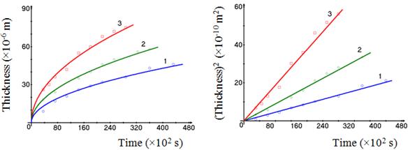
Fig. 8. Plots of layer thickness (left) and squared layer thickness (right) against time for both boride layers formed between a 30% Cr alloy and boron at a temperature of 850°C (1), 900°C (2) and 950°C (3)
In the case of a 5% Cr alloy, the temperature dependence of the growth-rate constant of the inner Fe2B layer in the time range 3600-14400 s when the FeB layer has still not formed between boron and the Fe2B layer is described by a relation of the Arrhenius type k1 = 7.00×10⁻⁶exp(–135.0 kJ mol–1/RT) m2s–1, where R is the gas constant (8.314 J mol–1K–1) and T is the absolute temperature (Fig. 9).With 15 and 30% Cr alloys, appropriate equations are
k1 = 1.95×10⁻⁹exp(–103.8 kJ mol–1/RT)m2s–1for the outer FeB layer,
k1 = 1.88×10⁻⁸exp(–123.1 kJ mol–1/RT) m2s–1for the inner Fe2B layer,
k1 = 2.32×10⁻⁸exp(–113.0 kJ mol–1/RT) m2s–1for both boride layers,
k1 = 2.53×10⁻⁸exp(–181.7 kJ mol–1/RT) m2s–1for the outer FeB–CrB layer,
k1 = 2.48×10⁻⁹exp(–127.7 kJ mol–1/RT) m2s–1for the inner Fe2B–Cr2B layer,
k1 = 1.18×10⁻⁸exp(–166.2 kJ mol–1/RT) m2s–1for both boride layers.
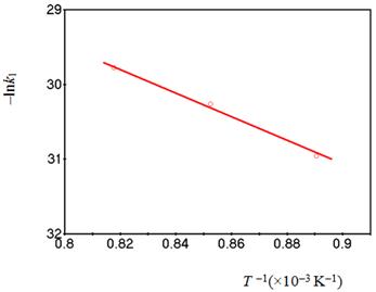
Fig. 9. Temperature dependence of the growth-rate constant of the Fe2B layer in the time range 3600-14400 s in the absence of the FeB layer from the Fe–5% Cr alloy-boron interface.
3.4. Microhardness of Boride Phases
Microhardness is 15.6 GPa for the FeB layer and 13.0 GPa for the Fe2B layer with a 5% Cr alloy, 17.4 GPa for the FeB layer and 14.4 GPa for the Fe2B layer with a 15% Cr alloy and 18.1 GPa for the FeB layer and 15.2 GPa for the Fe2B layer with a 30% Cr alloy. Considerable scatter (±1.5 GPa) of microhardness values within layer bulks is typical of both boride layers due to non-equilibrium conditions of their formation.
3.5. Dry Abrasive Wear Resistance of Boride Layers
The results of dry abrasive wear resistance tests are presented in Table 2. Boride layers with a microstructure of the second kind are seen to be much more wear resistant than those with a microstructure of the first kind. It is probably due to structural and morphological rather than compositional reasons because the difference in wear resistance, for example, of 5 and 30% Cr alloys, found from mass loss measurements, exceeds 40 times (0.03853 : 0.00090 = 42.8), while that in their chromium content is only 6 (30 : 5 = 6).
Table 2. Comparison of dry abrasive wear resistance values of boride layers formed on the surface of Fe–Cr alloy samples
| Alloy (%Cr) | Microstructure | Δmalloy base (g) | Δhalloy base (mm) | Δmboride layer (g) | Δhboride layer (mm) | r# |
| 5 | Kind I | 0.42335 | 0.47 | 0.03853 | 0.040 | 11.0 |
| 15 | Kind I | 0.31060 | 0.41 | 0.00695 | 0.010 | 44.7 |
| 30 | Kind II | 0.27740 | 0.37 | 0.00090 | ~0.003 | 308.2 |
#r=Δmalloy base / Δmboride layer
4. Conclusions
1. Two boride layers are formed on the surface of iron–chromium alloy (5, 15 and 30% Cr) samples during their thermochemical boriding at 850-950ºC and reaction times 3600-43200 s.
2. In the case of 5 and 15% Cr alloys, the outer layer bordering boron consists of the FeB compound, while the inner adjacent to the alloy base consists of the Fe2B compound. Each boride layer is a homogeneous phase. It is a microstructure of the first kind.
3. With a 30% Cr alloy, the outer layer comprises the FeB and CrB compounds, while the inner comprises the Fe2B and Cr2B compounds. Each boride layer is two-phase. It is a microstructure of the second kind.
4. The FeB and Fe2B layers occur on the surface of 5% Cr alloy samples sequentially, with the Fe2B layer being the first to form and grow. The continuous FeB layer is only formed if the thickness of the Fe2B layer exceeds, depending on the temperature of reaction, 100–180 µm.
5. With 15 and 30% Cr alloys, a reaction time of 3600 s is sufficient for both the FeB and Fe2B layers to form simultaneously.
6. The characteristic feature of the layers is a profound texture.
7. Their growth rate is close to parabolic.
8. Boride layers with the microstructure of the second kind exhibit a much higher dry abrasive wear resistance than those with the microstructure of the first kind.
Acknowledgments
The help of V. R. Sidorko, V. G. Khoruzha, L. V. Goncharuk, A. V. Samelyuk, V. V. Berezutsky, S. V. Bykova, L. A. Duma, I. G. Kondratenko, K. A. Meleshevich, E. S. Rabotina, D. M. Pashko and V. M. Petukh with preliminary work, maintenance of equipment and carrying out experiments is acknowledged with sincere gratitude.
References
- L. G. Voroshnin, L. S. Lyakhovich, Boriding of Steel, Metallurgiya, Moskwa, in Russian, 1978.
- A. G. Matuschka, Boronizing, Carl Hanser Verlag, Munchen, 1980.
- K. Holmberg, A. Matthews, Coatings Tribology, Elsevier, Amsterdam, 2009.
- M. Carbucicchio, G. Sambogna, Thin Solid Films 126 (1985) 299-305.
- C. M. Brakman, A. W. J. Gommers, E. I. Mittemeijer, J. Mater. Res. 4 (1989) 1354-1370.
- M. Kulka, P. Pertek, Appl. Surf. Sci. 214 (2003) 278-288.
- C. Martini, G. Palombarini, M. Carbucicchio, J. Mater.Sci. 39 (2004) 933-937.
- X. Tian, Y. Lu, S. J. Sun, Z. G. Wang, W. Q. Hao, X. D. Zhu, Y. L. Yang,Mater. Sci. Techn.24 (2008) 314-319.
- C. K. N. Oliveira, L. C. Casteletti, A. Lombardi Neto, G. E. Totten, S. C. Heck, Vacuum 84 (2010) 792-796.
- J. Jiang, Y. Wang, Q. Zhong, Q. Zhou, L. Zhang, Surf. Coat. Techn. 206 (2011) 473-478.
- I. Campos-Silva, JESTECH 15 (2012) 53-61.
- V. I. Dybkov, W. Lengauer, K. Barmak, J. Alloys Compd. 398 (2005) 113-122.
- J. Brandstötter, W. Lengauer, J.Alloys Compd. 262-263 (1997) 390-396.
- V. I. Dybkov, Reaction Diffusion and Solid State Chemical Kinetics, 2nd ed., Trans Tech Publications, Zuerich, 2010.
- V. I. Dybkov, Chemical Kinetics, IPMS Publications, Kyiv, 2013. Free online version http://www.dybkov.kiev.ua.


