
International Journal of Mathematics and Computational Science, Vol. 1, No. 4, August 2015 Publish Date: May 28, 2015 Pages: 166-173
On the Limiting Yield in Fullerene Synthesis
Кasumov М. М.*
V. I. Vernadskii Institute of General and Inorganic Chemistry of the Ukrainian NAS, Kyiv, Ukraine
Abstract
A comparative efficiency analysis of fullerene synthesis methods showed the advantage of the arc method and the output limit of arc discharge devices with various geometries: α = 19 ± 4% and 33%. In order to increase the output, working gas flow is introduced in the hollow electrode with arc discharge using a ceramic insulator (alundum crucible). Under such conditions, the formation time of fullerenes in the high-temperature space is longer and the cluster concentration is higher; therefore, the output of heavy fullerenes and product without amorphous component increases. It is planned to use, instead of alundum an insulator made of boron carbonitride.
Keywords
Alundum, Amorphous Soot, Boron Carbonitride, Formation Time, Gas-Plasma Flow, High-Temperature Insulator,
Hollow Electrode, Turbulence
Received: April 8, 2015
Accepted: April 22, 2015
Published online: May 27, 2015
@ 2015 The Authors. Published by American Institute of Science. This Open Access article is under the CC BY-NC license. http://creativecommons.org/licenses/by-nc/4.0/
Contents
1. Introduction 2. Comparative Analysis of Fullerene Synthesis Methods 2.1. Laser Method 2.2. Chemical Method 2.3. Arc Discharge Method 3. Varieties of Arc Discharge Devices for Fullerene Synthesis 3.1. Known Studies on Arc Discharge Synthesis 3.2. Results on Arc Discharge 4. Problem Solution Fullerene Arc Synthesis with a Hallow Cathode 4.1. On the Fullerene Formation Process in Arc Discharge 4.2. Arc Discharge in a Hollow Electrode with Working Gas flow (ADHE - WGF) 4.3. Synthesis of Fullerenes 4.4. On the Product of Synthesis by Arc Discharge in a ADHE-WGF 4.5. On the Mechanism of Fullerene Formation in ADHE-WGF 4.6. Estimation of the Efficiency of Fullerene Synthesis in ADHE-WGF 5. Conclusion Remarks Acknowledgment
1. Introduction
In the 1970s, the possibility of the existence of hollow C20, C60 clusters and their electronic structures were shown theoretically [1]. These carbon clusters, which were called fullerenes, were obtained experimentally in a supersonic helium stream by the action of a laser beam on the graphite surface [2]. Investigations showed that fullerenes are effective electron acceptors and form compounds with new properties with atoms of other elements. The discovered peculiarities show fullerenes and their derivatives to be a new class of molecules-compounds; the trends in physics, chemistry, biology, medicine and technology, which are originating on their basis, are also new. Therefore it was intended to carry out a technological revolution by modernizing the main spheres of activity through the use of fullerenes, their derivatives and composites based on them as the main material. To realize this idea, a search for and development of fullerene synthesis methods were initiated. In the past decades, the most important discovery was the Kratschmer arc method [3]. The relatively high efficiency of the method ensured successes in investigations of fullerenes [4], which extend to a marked degree the range of possible use of fullerenes with due regard for the works done in recent years (e.g. hydrolyzed fullerenes [5] can be used in liquids and salt solutions). To implement numerous projects, it is necessary to drastically increase the production of fullerenes [6-9]. However, with the existing synthesis methods, the cost of C60 fullerenes (in 1997-1999, a fall of 25-35% was observed) has been 20-40 times higher than the competitive cost of fullerenes for the beginning of their use at least in the most expensive spheres: pharmaceutics, diamonds, catalysts for over 20 years [6]. The cost of fullerenes as a product of the manufacturing chain includes, independent of synthesis method, the cost of the main stages: (1) making fullerene carbon black, (2) extracting fullerenes from carbon black (separating from the amorphous constituent) using solvents, (3) removing the solvent from the product [10]. Calculation shows that the cost of the first stage is under 1%. The main expenditures in terms of time, energy and the cost of expendables are associated with the use of environmentally harmful and expensive organic solvents.
The aim of this work is to survey literature on the existing fullerene synthesis methods, to choose an advantageous synthesis method and to show the development of an economical synthesis method. In the final part on the basis of preliminary trials is given a recommendation for the use of a ceramic insulator made of boron carbonitride.
2. Comparative Analysis of Fullerene Synthesis Methods
At the present time, the most commonly used fullerene synthesis methods are: laser, chemical and arc discharge methods. The common peculiarity of the methods is that fullerene synthesis takes place in an inert gaseous medium at the temperature 1500 < T < 7000 K [11] (low-temperature plasma conditions). The formation of nanostructures in a space with high temperature takes place by collision of carbon clusters. The process is affected by the Coulomb interaction of particles with opposite sign. The synthesis methods differ in fullerene formation mechanism.
2.1. Laser Method
The most efficient CO2 laser [12] has a relatively low efficiency; to use the laser widely, the cost of beam energy must be decreased by several fold [6]. A problem of the method is also the introduction of radiation into the reactor. Moreover, as was pointed out in [2], the vapor screening the portion treated with beam must be withdrawn during fullerene synthesis. However, the laser method, which is most convenient in controlling the beam energy, is used for the synthesis of pilot samples of nanostructures [8].
2.2. Chemical Method
This method of fullerene synthesis started with experiments on synthesis in torch flame. The method is based on the process of incomplete burnout of a mixture containing hydrocarbon, oxygen and ballast gas (He, Ar, N2). In the perfect form it is now FCC method [4,13]. The cost of the product is affected by the difficulty of singling out preassigned structures from the big range of synthesis products. They are hydrogenated and oxidized fullerenes, nanotubes and amorphous carbon black [10]. Detailed analysis of the mechanism shows that the formation of fullerenes takes place in reactions of polycyclic aromatic hydrocarbons (PAHs). In this case, the small fraction of coagulations of PAH molecules results in fullerene structures since during the transformation of PAH molecules, transformations of the intermediate product into carbon black at the point where a considerable curvature appears in growing molecule on the formation of internal pentagon take place with higher probability [6]. The synthesis temperature is about 2000 K, the yield is up to 20%, the velocity of the mixture over the torch is up to 0.5 m/s [13].
2.3. Arc Discharge Method
The method has the following parameters: 6000 ≥ T > 1500 K, velocity of gas-plasma jet in the reaction zone: over 10 m/s, small volume of the reaction space (interelectrode space and adjacent space: not over 0.2 L). It is similar in this to the laser method and has advantage over the chemical method. In contrast to the laser method, however, the carbon vapor formed at high temperature during synthesis is a plasma-forming element, which is necessary to maintain discharge. The mechanism of fullerene formation in arc discharge is similar to the laser method: it is coagulation in the gas phase on the collision of atoms and Cn clusters. The excess kinetic energy of the formed fullerene is removed, and the excess carbon atoms are annealed away on collision with the wall and buffer gas atoms. The yield is 15-23%. Secondary characteristics of the method: the ready availability and compactness of the advanced equipment give an additional advantage over other methods. Thus, the highest yield has been achieved at present by using electric arc, which has better prospects for increasing the efficiency of fullerene synthesis.
3. Varieties of Arc Discharge Devices for Fullerene Synthesis
The overwhelming majority of arc discharge devices were built by analogy with the original discharge device [3], in which low-pressure discharge is ignited between electrodes in the form of rods. In these devices, the space and duration of fullerene formation are determined by the value of the working interelectrode gap d and the length of the fullerene formation space, L ≈ 2 × d, bound up with it, which is covered during discharge within the time interval Δt ~ 10-3-4 s according to calculations [14]. In the case of this discharge mode, a small fraction of carbon vapor is transformed into fullerenes.
3.1. Known Studies on Arc Discharge Synthesis
The Afanasyev arc synthesis apparatus is known from numerous papers on the investigation of arc discharge and the properties of fullerenes. The plasma temperature during fullerene synthesis had been estimated. The temperature reaches T ~ 5 – 7×10³K. The radiation spectrum of fullerene plasma had been studied. A yield of ~ 15% was reached on the apparatus [11,1994].
On an automated precision apparatus for graphite arc evaporation it was shown that arc discharge for fullerene synthesis takes place at a pressure up to 0.11 MPa. Based on investigations, a mathematical model of arc reactor had been developed. In the model, the effect of atoms and small clusters (C1 - C4) on the formation of fullerenes had been considered. The limiting yield is 20-25%, and it was found that the value of the C70/C60 ratio is equal to 0.2 [15,1998]. In the work [16,2002], which was carried out on the same device at pressures of up to 0.3 MPa at the optimum values of interelectrode space and electrode consuption rate, a yield of up to 23% is given.
In the Churilov plasma apparatus, fullerene synthesis takes place in a discharge chamber, a cylider 40 mm in diameter and 590 mm in length. The discharge power supply is a 40 – 400 kHz high-frequency generator of up to 24 kW power. The temperature in the plasma medium was measured to be 2000 < T < 5000 K. When working with HF discharge in a working gas flow, it was assumed that fullerene synthesis takes place throughout the carbon plasma flow in coincidence with the helium flow; the yield is up to 20 % [7,2000].
On an arc synthesis apparatus [17,2004], measurements were made at discharge current magnitudes of 80 – 800 A with electrodes 6 – 20 mm in diameter. In the cathode were made five holes, through which a working gas flow was fed into the discharge space. The flow created a strong radial flow in the interelectrode space. In that case, the residence time of formed fullerenes in the interelectrode space and deposit formation decreased. Accordingly, the distruction of fullerents by the action of UV radiation decreased. The yield with electrode of 6 mm diameter at a discharge current of 80 A reaches ≈ 17%.
3.2. Results on Arc Discharge
In the above known papers, the discharge devices differ widely in general geometry, but the product yield obtained is:
α = (19 ± 4) %. (1)
The difference in the limits of yield measurement error for arc discharge devices is due to the fact that fullerenes are formed in a space with the highest plasma concentration: the interelectrode discharge space and the space adjacent (and turbulence) to it of approximately the same size are common to the above devices. The values in (1) show that the synthesis methods now in use have reached their limit. This entails the long persistence of high prices for fullerenes and retardation of the development of the fields of possible use of ullerenes.
4. Problem Solution Fullerene Arc Synthesis with a Hallow Cathode
The basis of the design of the dicharge device is cylindrical discharge chamber of stainless steel Fig 1(a). A tubular graphite cathode was placed axisymmetrically in the discharge chamber Fig 1(b).
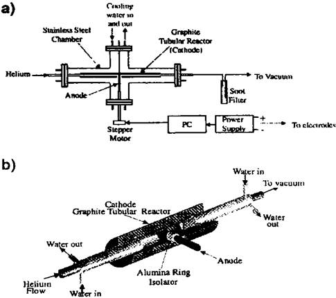
Fig. 1. Experimental setup [18]: (a) general view, (b) tubular reactor.
To electrically insulate the cathode from the anode, which is inserted through an opening in the middle of the tubular cathode, a ring of high-temperature ceramic (alundum) is used. On the ends of the discharge chamber were inserted water-cooled tubes for the feeding of helium and withdrawal of the synthesis product on the other end. When discharge is ignited, the plasma temperature in the interelectrode space settles at the highest value (T > 1500 K). According to the schematic in Fig. 1, one can imagine that the fullerene formation "line" begins from the middle of the cathode tube, where the initial laminar flow of working gas "dashes" against the anode. At the point synthesis process in a hollow cathode was taken into account in the development of processes in a discharge device (described below), in which fullerene formation at high temperature takes place along the full path length of encounter of the flow with the anode and in the near adjacent space. (This is just as in an ordinary water flow with small obstacle). A vigorous mixing of the working gas flow with small and medium carbon atoms and clusters (C2, C3, …), evaporated from the electrodes, takes place. On this portion in gas-plasma flow, a portion with turbulence appears, in which the formation process is accelerated. It follows that synthesis takes place in the other half of the hollow cathode. However, the temperature (T < 1500 K) and the rate of formation decrease with increasing distance from the interelectrode space. A yield of 33% was achieved with this device [18].
4.1. On the Fullerene Formation Process in Arc Discharge
Fullerene arc synthesis is a multievent process, the theory of which has not been carried to completion. According to general concepts, the Cj fullerene formation process takes place in the discharge space at 1500 – 5000 K during diffusion as a result of collisions followed by coalescence of nanoparticles. Fullerene synthesis is conventionally represented as series of acts of attachment of small Ck, Ci clusters of carbon vapor from the heated portions of the electrodes and the subsequent kinetic excess energy relaxation of coalescing particles in inverse processes, annealing-away of nf ·Cf clusters. Conventional synthesis scheme:
Сj = Ск+∑|i ni∙Ci - ∑|f nf ·Сf, (2)
where Ck is the initial fullerene cluster formed in the interelectrode space, the coefficients ni, nf are integers The clusters in the scheme (2) are summed with respect to the subscripts i and f. According to the scheme (2), the formation parameters of each Cj fullerene also develop on the conventional path. The fullerene formation parameters are formed from the sum of individual segments: duration of the formation process, Тj = ∑|jtСj, and formation path length Hj = ∑|j hСj.
In arc discharge, the diffusion nature of spatial motion with temperature decrease from radius gives a spread of clusters in path parameters, in mass and quality of the product. In arc discharge, amorphous carbon black accounts for a larger fraction of the product (> 50%).
From the analysis of the existing concepts it may be assumed that the product of other quality can be obtained in a space with high temperature, in which longer duration and length of fullerene formation path with turbulent portions are ensured. The space with such peculiarities has a circular symmetry at the minimal energy consumption.
4.2. Arc Discharge in a Hollow Electrode with Working Gas flow (ADHE - WGF)
To ensure continuous synthesis process, a stock-produced TDM-317 as welding power source with dropping current-voltage characteristic and a pulsed arcing stabilizer (PAS) were used jointly. The TDM-317 + PAS circuit continuously holds plasma in the interelectrode space, also at the moments of passage of current and voltage through zero [19].
Fig. 2. Projections of parts of the hollow electrode arc discharge device with conditional path of fullerenes formation A→B →C → D.
In the works [20,21], fullerene synthesis was caried out in a chamber of 68 mm diameter (h = 150 mm) on the discharge device shown in Fig. 2: graphite electrode 1 for emission spectrum analysis (diameter 6 mm), graphite electrode 2 (cavity diameter 15 mm, h = 15 mm) with slits through which working gas (He) enters the electrode cavity. In the design, the part 3 is a graphite cover. Electrical insulation between the electrodes 1 and 2 is provided by a high-temperature ceramic, an alundum crucible 4. An extra function of crucible is heating the working gas that enters the discharge space. The working gas coming from the free space heats on the passage of gas-pasma flow and discharge radiation over the surface of the crucible, which heats up on thermal contact with the heated electrode portion. The parts 5 and 6 of common steel apply potential to the electrode 2 and fasten the construction together into a whole. The part 7 is the chamber wall.
The electrode holders and chamber walls are water-cooled. Fig. 2 does not show the device that aligns the electrode 1, which is consumed during discharge, relative to the cavity of the electrode 2. It is seen from Fig. 2 that the synthesis product leaves the cavity against convection; therefore, the fullerene formation process is longer.
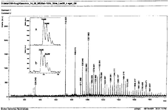
Fig. 3. The peak values of Mass spectrum of fullerenes obtained in HEAD-WGF depend on m/z.
4.3. Synthesis of Fullerenes
Fullerenes were synthesized with the helium flow rate q = 0.3 L/min at discharge currents of 60, 80, 70, 70 A. Dischage with the current I = 60 A was switched on, but it was switched off after 30 – 40 min because no electrode consumtion was observed. This condition was taken as the lower discharge current limit. At the discharge current I = 80 A, fullerene carbon black was obtained, which showed an amorphous constituent in benzene. The precipitate was removed by filtration. This condition for discharge current is the upper limit for the device. The other discharge data are given below.
At the optimal current magnitude I = 70 A, discharge was switched on for t = 5 and 7 min. The discharge voltage varies smoothly during synthesis. As the electrode burns up the voltage increases. To retain the optimal discharge conditions, the electrode was displaced. For these conditions, the measured electrode consumption rate was v ≈ 18×10-3g/min, and 8×10⁻³ and 12×10-3g deposits formed in the hollow electrode, the mass of them being 5 – 6 times smaller than the usual one. In air, the deposits were easily removed. The fullerene carbon black was removed from the chamber walls and immersed in benzene. The rapid and complete dissolution of carbon black was unexpected. The solution turned red-brown, which is typical of fullerene solution, but there was no precipitate in the solution. In the ordinary-discharge product, filtration takes a longer time because fullerenes are extracted in the solvent through a layer of amorphous carbon black, the extraction being at a minimum in this particular case. With allowance for deposit, the synthesis product (fullerenes) accounts for up to 90% of the mass of consumed carbon.
4.4. On the Product of Synthesis by Arc Discharge in a ADHE-WGF
The composition of the product of synthesis by ADHE-WGF (fullerite) was determined on an AutoFlex apparatus (Bruker, Germany) from a time-of-flight mass spectrum (MS). A MS of fullerenes with negative charge for a product obtained in HEAD -WGF under optimal conditions (discharge current I~ = 70 A, discharge voltage V~ ≈ 20 V; laser beam parameters: q = 2,6×10 -6J, f = 10 s-1) is shown in Fig. 3. As can be seen, the lines in this series follow at the interval ∆ (m/z) = 24 amu = 2mc, which is usual for fullerene spectrum. It is seen from Fig. 3 that the MS consists of background bands, which differ in height and width, bands of medium protonated clusters (C26, C27, C28), C60, C70, C72 and a series of C74+2n lines, where n = 0-40. In the spectrum, the lines of stable nanostructures, which accumulated during discharge on the cooled walls of the chamber: C60-, C70-,…, C78-, C84-,.., C90-, C96-, C112-,…, C150- stand out in the value of the peaks.
It is easy to notice that the peak values in the MS of fullerenes in Fig 3 are in agreement with the formation mechanism of cheme (2) and another detailed presentation proposed: the peak values of fullerenes decrease with increasing mass, but the decrease in peak values in ADHE-WGF is smaller as compared with ordinary-arc-discharge spectrum. An important peculiarity of the spectrum of ADHE -WGF, which contradicts the above one, is that the peak value of C84 fullerene exceeds that of the C70 fullerene. The spectrum of fullerenes with positive charge ends with the C84+fullerene peak, but the background spectrum has an extension at m/z > 1800 u.
4.5. On the Mechanism of Fullerene Formation in ADHE-WGF
As was pointed out above (p. IV, A), fullerenes begin to form on collisions of carbon atoms, ions and small C2, …, C4 clusters by the action of a turbulent evaporation flow from the surface of the electrodes. But in a hollow electrode, the turbulence under the action of working gas flow is higher, and the process occurs with the participation of helium atoms via forward and back reactions [23]. As was pointed out, another distinction of the MS of ADHE-WGF from ordinary-discharge MS is background. The structures that create a background in the MS of ADHE-WGF don’t affect the transparency of the benzene solution of fullerene carbon black. The background is created by nanostructures formed as a result of "re-formation" of fullerenes and annealing away of fragments, which become just a "nanobackground". The nanobackground peaks in the mass spectrum 24 ≤ m/z < 2000 u have a value of up to 2.0 – 3.5 % of the peak value of C60. The MS of the product of ADHE-WGF at the discharge current I = 70 A without filtration coincides with the spectrum obtained after double filtration. The result is confirmed by the MS of fullerene carbon black synthesized at I = 80 A. There is a background in the spectrum of positive and negative ions, and the background is larger for the product obtained at higher discharge current.
4.6. Estimation of the Efficiency of Fullerene Synthesis in ADHE-WGF
To estimate the efficiency of the process, the equation:
Р = 60 ∙ v ∙ Y ∙ r, (3)
Was employed, where the electrode consumption v was determined above; Y ≈ 1, and r = t/ (t + t0) is the ratio of synthesis process and cycle durations. Calculation from (3) gives the value: P ≈ 0.8 g/h. But the mass of the product was smaller than the calculated one because of product loss in the synthesis space. Therefore, the efficiency estimates given in the paper were obtained with allowance for the C-C bond energy of the C60 fullerene. A value of the order of ≈ 0.9 % was obtained.
G. Geometrical Factor in Fullerene Formation
In arc discharge, the length of fullerene formation path is estimated from the equation:
L0 = (1÷3) × ∆, (4)
where ∆ is working interelectrode gap ∆ = 1 – 7 mm [4], and the length of fullerene formation path L0 ≈ 15 mm.
A common estimation of the length of formation space in the device for ADHE-WGF is given on the basis of the size of the electrodes:
L1 = [H + (Ф – ф) • 0.5]• K, (5)
where H is the cavity depth, Ф is the cavity diameter, ф is the consumed rod diameter, gas flow turbulence factor K > 1[24]. The calculations give formation path L1 ≈ 25 mm.
A more detailed examination of the formation path, which takes into account the cavity geometry and gas plasma thermodynamics, gives the path:
L1 * ≥ 100 mm. (5*)
In this case the fullerene formation path is a helix, which has 2-3 turns.
Comparison of the values in (4) and (5), (5*) shows an advantage of the method with hollow electrode over that with ordinary discharge: the fullerene yield is higher at the longer length of nonlaminar formation path.
5. Conclusion
• The electric arc method has an advantage over the laser and chemical methods. In the 1990s, the maximum fullerene yield (19 ± 4) % was achieved by arc synthesis, and the major part of the synthesis product is amorphous carbon black.
• In 2005 [18], a fullerene yield of 33% in a hollow graphite tubular reactor was attained.
In 2007 [20], to increase the efficiency of fullerene synthesis, arc discharge in a hollow electrode with working gas flow (ADHE – WGF) from a space with high-temperature insulator was used for the first time; it was shown that in this discharge, carbon vapor is transformed into fullerenes without amorphous carbon black formation.
Remarks
The results presented in the paper have been obtained in successful series of measurements on an ADHE-WGF device with high-temperature alundum insulator. But in most cases of unsuccessful switch-ons, the alundum crucible crackled after one or three switch-ons at a discharge current of up to 100 A for several minutes. To complete the technology, an insulator had to be selected which can sustain multiple heating-cooling cycles at an operating temperature of the process of 1500-2300 K during 30-60 minutes. The search led us to a high-temperature boron carbonitride insulator [25–27]. It is a material of light grey to dark color. The material is similar to graphite or chalk in mechanical properties. Blanks of this material can be machined by turning to a wall thickness of 3 mm, which was required for reducing the thermal inertia of the part. When the discharge device was assembled, any mechanical loads on the crucible were excluded. The crucible with the parts of the device as an assembly was placed in the discharge chamber. After several switch-ons under discharge conditions the crucible retained its dimensions and had no cracks.
Acknowledgment
The author is grateful to the research workers of the I. N. Frantsevich Institute of Materials Science Problems of the Ukrainian NAS A. S. Firstov, O. N. Grigoryev and V. V. Lychko for the useful suggestions and remarks in the discussion of the task to be performed and for the blanks for the boron carbonitride crucible delivered within a short time.
References
- D. A. Bochvar, E. G. Galpern. / On hypothetical systems: carbo- dodecahedron, s-icosahedron and carbo-s-icosahedron. Reports of the USSR Academy of Sciences.-1973.-Vol.209.-P.610-612.
- Kroto H. W., Heath I. R., O’Brien S. C., Curl R. F., Smally R. E. C60: Buckminsterfullerene./ Nature.-1985.-V.318.-P.162-163.
- Kratschmer W., Lowell D. Lamb, Fostiropulos K.,Donald R. Huffman. Solid C60: a new form of carbon. / Nature.-1990.-V.347.-No.6291. - P.354-358.
- L. N. Sidorov, M. A. Yurovskaya et al. - Fullerenes: Tutorial /М.: Publishing house«Ekzamen», 2005.- 688p.
- D. G. Letenko, V. A. Nikitin, K. N. Semenov, N. A. Charykov, A. S. Ivanov. Electrical conductivity of fullerenol aqueous solutions obtained by direct oxidation./Jour. Phys. Chem.-2012.- Vol.86, No.12.- P.1944-1952.
- Bogdanov A., Dreininger D., Dyuzhev G. REVIEW. Prospects for the development of industrial methods of fullerenes production./ Technical Physics Journal.-2000.Vol.70.В.5. P.1-7.
- Churilov G. Plasma synthesis of fullerenes./ Instruments and Experimental Techniques.-2000.-No.1. -P.5-15.
- Whitesiders J., Eigler D., Anders R. et al. Nanotechnology in the Next Decade. Prediction of the Line of Research./ Translated from English.-М.: Mir, 2002.- 292 p.
- V. G. Udovitskiy, A. Yu. Kropotov, V. I. Farenik. Development of plasma methods of fullerenes synthesis. /Physical Surface Engineering. - 2012, Vol.10, No. 4, P. 434 — 447.
- Grushko Yu. S., V. P. Sedov, Shilin V. A. Technology for production of pure fullerenesС60, С70 and higher fullerenes concentrate. / Journal of Practical Chemistry -2007. - Vol.80, ed.3.-P.450-457.
- Afanasyev D., Blinov I., Bogdanov A., Dyuzhev G., Karataev V., Kruglikov A. Formation of fullerenes in arc discharge. /Technical Physics Journal.1994. - Vol.64.-В.10. P. 76-90.
- Afanasyev D., Baranov G., Belyaev A., Dyuzhev G., Zinchenko A. Production of fullerenes by graphite evaporation with stationary CO2 laser. / Letters in the Technical Physics Journal.-2001.-Vol.27.-В.10.- P.31-36.
- H. Murayama, S. Tomonoh, J. M. Alford, M. E. Karpuk. Fullerene production in tons and more: from science to industry./ Fullerenes, nanotubes, and carbon nanostructures / Vol.12, No.1 & 2, pp. 1-9, 2004.
- N. I. Alekseyev, G. A. Dyuzhev. Effect of small clusters on the Process of two-ring cluster conversion into fullerene./ Technical Physics Journal.-2002.- Vol.72, ed.5.-P. 130 -134.
- A. V. Krestinin, A. P. Moravsky. Mechanism of fullerene synthesis in the arc reactor./Chem. Phys. Lett., 1998, 286, 479 – 484.
- Sokolov E., Babenko S., Zakharov D., Moravskiy A., Piven I., Tarasov B., Fursikov P. Effect of conditions of fullerene- containing soot preparation on its microwave properties and yield of fullerenes. /Proceedings of the Academy of Sciences. Chemical series -2002.- No.6.-P.860-862.
- Dubrovsky R., Bezmelnitsyn V. New Approach in Synthesis of Carbon Allotropes in Large Quantities. / Fullerenes, Nanotubes and Carbon Nanostructures.-2004.-V.12. – part 1-2.- P.17-24.
- Sesli A., Cicek B., Oymael M. Fullerene production in a graphite tubular reactor./ Fullerenes, Nanotubes and Carbon Nanostructures.- 2005.-V.13.-N 1. P.1-11.
- B. Ye. Paton, I. I. Zaruba, V. V. Dymenko, A. F. Shatan, Welding Power Source with Pulse Stabilization of Arcing (in Russian). "Ekotekhnolohiya", Kyiv (2007). - 248.
- Kasumov M. M., Pokropivnyy V. V. Increasing the yield of fullerenes in arc discharge under the influence of gas flow in hollow electrode./ Technical Physics Journal.- 2007.- Vol.77, ed.7.-P.136-138.
- Kasumov M. M., Solomenko O. V. On the path of fullerene Formation in hollow arc disharge electrode plasma./ Bulletin of Taras Shevchenko Kyiv National University, Phys.-mat. Science series, 2012, No. 1, P.267-270.
- Borodin V., Truhacheva V. Thermal stability of fullerenes. /Letters in the Technical Physics Journal.- 2004.- Vol.30.- Ed.14.- P.53-55.
- Shpak A. P., Kunitskiy Yu. A., Karbovskiy V. L. Cluster and nanostructure materials./ Kiev. "Akademperiodika". -2001. -Vol. 1.
- Abramovich G. N. Applied gas dynamics. Part.1.М.: Nauka.1991
- O. N. Grigoryev, N. D. Bega, T. V. Dubovik, O. D. Shcherbina, V. I. Subbotin, V. A. Kotenko, A. A. Rogozinskaya, T. V. Mosina, I. L. Berezhinskii, V. V. Lychko, Dekhtyaruk, A study of the effect of the oxide additives ZrO2 and SiO2 on phase formation processes and the properties of hot-pressed composites based on boron carbonitrides, Ogneupory i Tekhnicheskaya Keramika, no 3, pp 18- 26 (2009).
- O. N. Grigoryev, T. V. Dubovik, N. D. Bega, O. D. Shcherbina, V. I. Subbotin, V. A. Kotenko, E. V. Prilutskii, A. A. Rogozinskaya, V. V. Lychko, I. L. Berezhinskii, L. M. Udovenko, Effect of silicon-containing additives on the phase composition and properties of boron carbonitride based composites, Poroshkovaya Metallurgiya, no 3/4, pp 89-97 (2011).
- O. N. Grigoryev, T. V. Dubovik, V. I. Subbotin, V. V. Lychko, O. V. Koroteev, Ukrainian patent for useful model № 81192, 25.06.2013.


