
International Journal of Mathematics and Computational Science, Vol. 1, No. 4, August 2015 Publish Date: May 23, 2015 Pages: 160-165
Flow and Heat Transfer over a Solid-Porous Block in a Channel
Neda Janzadeh, Mojtaba Aghajani Delavar*
Faculty of Mechanical Engineering, Babol Noshirvani University of Technology, Babol, Iran
Abstract
In this study the effects of solid block location inside a porous block over heat transfer and fluid flow was investigated numerically. The two dimensional lattice Boltzmann method was applied for all numerical simulations. The fluid flow in the porous media was simulated by Brinkman-Forchheimer model. The results show that the flow behaviour and heat transfer are sensitive to the variation of the solid block location. It is illustrated that an increase in contact surface between solid block and porous block would increase the heat transfer. The maximum heat transfer occurs for solid block located in the centre of the porous block.
Keywords
Heat Transfer, Lattice Boltzmann Method, Thermal Conductivity, Porous Block
Received: April 7, 2015
Accepted: April 20, 2015
Published online: May 22, 2015
@ 2015 The Authors. Published by American Institute of Science. This Open Access article is under the CC BY-NC license. http://creativecommons.org/licenses/by-nc/4.0/
1. Introduction
The forced convection heat transfer in a channel with porous structures has used in many engineering applications such as micro-thrusters, transpiration cooling, solid matrix or micro-porous heat exchangers, electronic cooling, chemical catalytic reactors, heat pipe technology, filtering, fuel cells, air heaters, insulation, porous bearing, nuclear reactors, and many others.
Kuo and Tien [1] studied numerically the laminar force convection in a channel with discrete heat sourcesarranged on the bottom wall. They reported a two to four times increase of heat transfer obtained as compared to the flow in a clear duct.Hwang [2] experimentally studied the fluid flow and heat transfer in a channel with porous blocks attached on both the upper and bottom walls in a staggered manner. Angirasa [3] simulated numerically the force convection in a channel filled with metallic fibrous materials. He reported significant enhancement in the heat transfer in a channel due to porous substrate. Huang et al. [4] reported numerical results for force convection in a channel using multipleheatedblocks. Their results showed the recirculationcaused by porous-covering block will augment the heat transfer rate significantly. Kaviany [5] used the Brinkman extendedDarcy model toinvestigate the laminar flow in a porous channel with isothermal parallel plate. Poulikakos and Kazmierczak [6] analytically simulated the enhancement of forced convection in a parallel plate ducts and in circular pipes with constant wall heat flux by using porous materials. The Lattice Boltzmann Method (LBM) is a powerful numerical technique based on kinetic theory for simulation of fluid flows and modelling the physics in fluids [7-9]. Guo and Zhao [10] simulated numerically the incompressible flows through porous media by using lattice Boltzmann method.The method was successfully applied to simulatethe flow pattern and thermal field inside a T-micromixer with a porous block by Delavar [11].Delavar et al. [12] used the Lattice Boltzmann Method (LBM) to investigate numerically the effects of heater location and entropy generation. In present study the effects of solid block location with porous layer in channel on heat transfer were studied numerically by using LBM.
2. Numerical Model
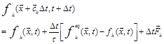
The general form of lattice Boltzmann equation with nine velocities in two dimension, D2Q9, with external force can be written as [8]:
 (1)
(1)
where ![]() is the external force,
is the external force, ![]() is the equilibrium distribution function,
is the equilibrium distribution function,![]() is the lattice time step,
is the lattice time step,![]() denotes the discrete lattice velocity in direction k,
denotes the discrete lattice velocity in direction k,![]() denotes the lattice relaxation time,
denotes the lattice relaxation time,![]() is the lattice fluid density,
is the lattice fluid density,![]() is weighting factor.
is weighting factor.
The local equilibrium distribution function verifies the type of the solved problem. Eq. (1) is usually solved in two steps, the collision and streaming steps. The collision step models a variety of fluid particle interactions like collisions and calculates new distribution functions according to the distribution functions of the last time step. In addition it models the equilibrium distribution functions, which are calculated with
![]() (2)
(2)
More details about LBM is and its implementation in codes are presented in [8].
The thermal LBM utilizes two distribution functions, ![]() and
and![]() , for flow and temperature fields, respectively. The
, for flow and temperature fields, respectively. The ![]() distribution function is as discussed above; the
distribution function is as discussed above; the ![]() distribution function for thermal field is defined as [8]:
distribution function for thermal field is defined as [8]:
![]() (3)
(3)
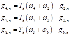
The![]() corresponding equilibrium distribution functions are as below:
corresponding equilibrium distribution functions are as below:
![]() (4)
(4)
The flow properties are defined as (i denote the component of the Cartesian coordinates):
![]() (5)
(5)
The Brinkman-Forchheimer equation for flow in porous regions is written as [10,11]
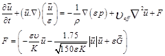 (6)
(6)
where![]() is the kinematic viscosity, K is the permeability,
is the kinematic viscosity, K is the permeability,![]() is the porosity,
is the porosity,![]() is the effective viscosity, and G is the acceleration due to gravity. F is the total body forcewith the widely used Ergun’s relation [13]. The corresponding distribution functions for porous medium are as same as Eq. 1. But the equilibrium distribution functions and the forcing term are [10]:
is the effective viscosity, and G is the acceleration due to gravity. F is the total body forcewith the widely used Ergun’s relation [13]. The corresponding distribution functions for porous medium are as same as Eq. 1. But the equilibrium distribution functions and the forcing term are [10]:
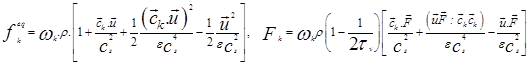 (7)
(7)
The fluid velocity ![]() in the forcing term
in the forcing term ![]() is defined as:
is defined as:
![]() (8)
(8)
According the above equations ![]() is related to
is related to![]() , so Eq. (8) is nonlinear for the velocity. A temporal velocity
, so Eq. (8) is nonlinear for the velocity. A temporal velocity ![]() is used to solve this nonlinear problem [10]:
is used to solve this nonlinear problem [10]:
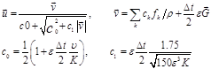 (9)
(9)
If the above temporal velocity be used in LBM simulations, no singularity and uncontrollable nonlinearity will happen in the solving procedure and LBM code will be converged to final solution, more details are presented in [14].
![]() is the effective thermal conductivityof the porous medium should be recognized for proper investigation of conjugate convection and conduction heat transfer in porous zone, which generally depends on the porous solid structure and the fluid which passes through it. The effective thermal conductivity of the porous mediumwas calculated by [15]:
is the effective thermal conductivityof the porous medium should be recognized for proper investigation of conjugate convection and conduction heat transfer in porous zone, which generally depends on the porous solid structure and the fluid which passes through it. The effective thermal conductivity of the porous mediumwas calculated by [15]:
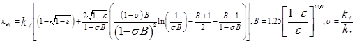 (10)
(10)
3. Boundary Condition
The unknown distribution functions are those toward the domain due to fact that from the streaming process the distribution functions out of the domain are known. Regarding the boundary conditions of the flow field, the solid walls are assumed to be no slip, and thus the bounce-back scheme is applied. For example for flow field in the north boundary the following conditions are used:
![]() (11)
(11)
where![]() is the lattice on the boundary.The unknown distribution functions for isothermal boundaries such as anupper hot wall, evaluated as:
is the lattice on the boundary.The unknown distribution functions for isothermal boundaries such as anupper hot wall, evaluated as:
 (12)
(12)
The unknown distribution functions for adiabatic boundary condition such as upper wall are evaluated as:
![]()
4. Computational Domain
The Computational domain consists of a square porous block with a hot solid block located in a channel, Fig. 1. The simulation parameters are shown in the Table 1.
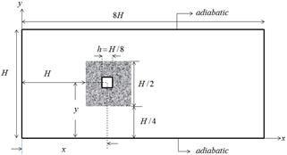
Figure 1. The computational domain
Table 1. Simulation Parameters
| H1.0cm | L8.0cm |
| Re 40-60-80-100 | Tinlet200C |
| x/h 8,9,10,11,12 | Twall solid block400C |
5. Validation and Grid Independency Check
In this study, fluid flow and heat transfer over a hot solid block inside a porous block in a channel were simulated by using lattice Boltzmann method.Figure 2compares well the velocity profile for flowin a porous channel with result by Seta et al. [15].Table 2 shows the Nusselt numbers calculated by LBM and Kays and Crawford [16], good agreement is observed.
Table 2. Comparison of averaged Nusselt number between LBM and Kays and Crawford [16]
| q"2/q"1 | 0.5 | 1.0 | 1.5 | |
| Nu1 | Kays and Crawford[16] | 17.48 | 8.23 | 11.19 |
| LBM | 17.25 | 8.16 | 11.10 | |
| Nu2 | Kays and Crawford[16] | 6.51 | 8.23 | 7.00 |
| LBM | 6.49 | 8.16 | 6.91 | |
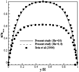
Figure 2. Comparison of velocity profile for porous channel between LBM and seta et al. [15]
6. Results and Discussion
In the present work the force convection heat transfer over a hot solid block inside a square porous block located in a channel was simulated. The thermal Lattice Boltzmann model with nine velocities was used to solve the problem. The effect of solid block location in x direction on heat transfer and fluid flow was studied.
The effect of solid block location on the thermal performance of the channel is illustrated in Fig. 3. This figure shows the velocity and temperature contours for variations of solid block location inside a square porous block in x direction: x/h=8, 9, 10, 11, 12. The velocity contours show that a large amount of fluid passes through the gaps between the porous block and the upper and bottom walls, and only a small portion of the fluid penetratesvia the porous blocks. The velocity ratio in the clear passages 4.2 and inside a porous block is 0.6. From this figure, it is found that in the model which solid block is located in center of porous block (x/h=10) the maximum temperature is observed. In this condition, all sides of solid block are covered by porous media. Porous parts have greater effective thermal conductivity than clear parts (Eq. 10).So in x/h=10 the maximum heat transfer occurs between solid block and adjacent flow passing through porous block.
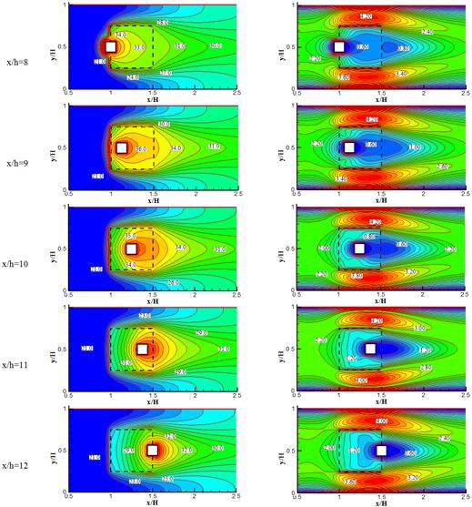
Figure 3. Left) temperature contours (oC), right) Velocity contours (U/Uinlet(Re=50)) for different solid block location in x direction
The presence of porous media increases the effective thermal conductivity. Consequently with increasing the contact surface between solid block and porous media, the heat transfer increases and then the fluid temperature will increase. So in Fig. 3, the temperature of fluid in cases which some parts of solid block are not surrounded by porous media (x/h=8, 12) are lower that other ones (x/h=9, 10, 11).
As respected a region with low velocity will form behind of solid block (zones with blue colour in velocity contours, Fig. 3).When the solid block moves to the right of the channel, the zone with low velocity inside the porous block will decrease. The convection heat transfer is consisted of conduction and advection. When the velocity of fluid decreases inside the porous block, the conduction heat transfer in porous block increases. So the fluid temperature will increase due to higher thermal conductivity of porous parts (Eq. 10). In Fig. 3 it can be seen that with increasing the low velocity zone inside a porous block, the effect of conduction on heat transfer increases, therefore the fluid temperature increases. As a result the fluid temperature for x/h=8 is more than x/h=12 and for x/h=9 is more than x/h=11.
The average temperature of fluid flow at various solid block locations inside a square porous blockin x direction are illustrated in Fig. 4. The maximumaverage fluid temperature is obtained for the solid block at x/h=10. With increasing the presence of porous media contact with solid block, the effective thermal conductivity increases. At higher values of thermal conductivity, the heattransfer from solid block to working fluid and fluid temperatureincrease; accordinglythe average fluidtemperature forthe caseswhich all side of solid block are surrounded with porous media is greater than other ones. In Fig. 4, it can be seen that the average fluid temperatures at x/H=9, 10, 11aremore than x/H=8, 12. As mentioned the models which have more low velocity regions inside the porous block havehigher fluid temperature. So the average fluid temperatures at x/h=8, 9 are more than x/h=12, 11, respectively.
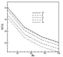
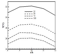
Figure 4. Averaged fluid temperature for various Reynolds number at different solid block location in x direction
7. Conclusion
In this paper the fluid flow and thermal performance in a channel with solid block inside a square porous block was simulated numerically using Lattice Boltzmann method. The effects of solid block location in x direction on the flow field and heat transfer were investigated. The results show that the increase of the contact surface between solid block and porous media will increases the fluid temperature. So the maximum fluid temperature occurs for solid block located in the center of the porous block. The fluid temperature increases for solid block which is located at left edge of porous block. In these condition, the low velocity zone inside the porous block increases which causes the conduction heat transfer enhancement and then the fluid temperature will increase
Nomenclature
c: discrete lattice velocity
Da : Darcy number ( KH−2 )
F: external force
f: distribution function for flow
g: distribution function for temperature
H: characteristic Height, m
K: Permeability
k: thermal conductivity, W/m2.K
T: Temperature, K
u: velocity component in x direction, m/s
v: velocity component in y direction, m/s
x: axial coordinate
Greek Symbols
![]() : is the porosity of porous media
: is the porosity of porous media
![]() : kinematic viscosity, m2/s
: kinematic viscosity, m2/s
![]() : Density, kg/m3
: Density, kg/m3
![]() : relaxation time
: relaxation time
![]() : Dynamic viscosity, Pa.s
: Dynamic viscosity, Pa.s
Superscripts
eq: equilibrium distribution function
Subscript
eff: Effective
i: dimension direction
in: Inlet
k: lattice model direction
out: Outlet
![]() : weighting factor
: weighting factor
References
- Kuo S. M.,TienC.L., 1988, Heat transfer augmentation in a foam-material filled duct with discrete heat sources, in:Proceedings of the Thermal Phenomena in Electronics Components.
- Hwang J.J., 1997. Turbulent heat transfer and fluid flow in a porous-baffled channel. J. Thermophys. Heat Transfer., 11: 429e436.
- Angirasa D., 2002. Forced convective heat transfer in metallic fibrous materials, ASME J. Heat Transfer., 124 : 739–745.
- Huang P.C.,Vafai K., 1994. Analysis of forced convection enhancement in a channel using porous blocks. AIAA J. Thermophys. Heat Transfer., 18: 563–573.
- Kaviany M., 1985. Laminar flow through a porous channel bounded by isothermal parallel plate. Int. J. Heat MassTransfer., 28: 851–858.
- Poulikakos D.,Kazmierczak M., 1987. Forced convection in a duct partially filled with a porous material. ASME J. HeatTransfer., 109: 653±662.
- Succi S., 2001. The Lattice Boltzmann Equation for Fluid Dynamics and Beyond. ClarendonPress. Oxford.
- Mohammad A. A., 2011. Lattice Boltzmann Method, Fundamentals and Engineering Applications with Computer Codes. Springer. London. England.
- Kao P. H., Chen Y. H., Yang R. J., 2008. Simulations of the macroscopic and mesoscopic natural convection flows within rectangular cavities, International Journal of Heat and MassTransfer., 51: 3776–3793.
- Guo Z.,Zhao T.S., 2002. Lattice Boltzmann model for incompressible flows through porous media, Phys. Rev., E 66: 036304.
- Delavar M. A., 2012.Investigation ofporousblockporosity onflow andentropygenerationinside a T-MicromixerusinglatticeBoltzmannmethod. Applied Mechanics and Materials., 282: 229-231.
- Delavar M. A.,Farhadi M., Sedighi K., 2011, Effect of discrete heater at the vertical wall of the cavity over the heat transfer and entropy generation using LBM, Thermal Science, 15(2):423-43.
- Ergun S., 1952. Chem. Eng. Prog., Vol. 48, p. 89.
- Seta T.,Takegoshi E., Okui K.,2006, Thermal lattice Boltzmann Model for Incompressible Flows through Porous Media, Journal of Thermal Science And Technology, 1: 90-100.
- Jiang P.X., Lu X.C., 2006. Int. J. Heat and Mass Transfer, Vol. 49: p. 1685.
- Kays W. M., Crawford M. E., 1993. Solutions Manual, Convective Heat and Mass Transfer, third ed., McGraw-Hill, New York, Problem 9-1.


