
American Journal of Educational Science, Vol. 2, No. 3, May 2016 Publish Date: Oct. 19, 2016 Pages: 16-28
Mechatronics Subsystems' Classification, Role, Selection Criteria and Synergistic Integration in Overall System Design
Farhan A. Salem1, 3, *, Ahmad A. Mahfouz2, 3
1Mechatronics Engineering Program, Department of Mechanical Engineering, College of Engineering, Taif University, Taif, Saudi Arabia
2Department of Automatic and Mechatronics Systems, VladimirState University, Vladimir, Russian Federation
3Alpha Center for Engineering Studies and Technology Researches, Amman, Jordan
Abstract
This paper summarizes, Mechatronics system design education oriented methodology, and focuses on role, classification and selection criteria of each subsystem, and it's integration in overall system design, the main design terminologies and concepts are introduced, discussed and integrated with overall design. The paper is intended to support engineering educators and help non experienced student or group of students to integrate multidisciplinary knowledge and skills, in various stages, in solving Mechatronics design integrated tasks.
Keywords
Mechatronics Design Education, Interdisciplinary, Concurrency, Selection, Synergy Integration
Received: June 20, 2016
Accepted: July 20, 2016
Published online: October 19, 2016
@ 2016 The Authors. Published by American Institute of Science. This Open Access article is under the CC BY license. http://creativecommons.org/licenses/by/4.0/
Contents
1. Introduction 2. Mechatronics Design - Concepts and Terminologies 3. Proposed Guideline for Mechatronics Systems Design Education Oriented Methodology 3.1. The Pre-study Process - Problem Statement 3.2. Conceptual Design 3.3. Modeling, Simulation, Analysis and Evaluation 3.4. Prototyping, Testing, Evaluation and Optimization 3.5. Manufacturing and Commercialization 3.6. Support, Service and Market Feedback Analysis 4. Conclusions
1. Introduction
The modern advances in information technology and decision making, as well as the synergetic integration of different fundamental engineering domains caused the engineering problems to get harder, broader and deeper. Problems are multidisciplinary and solving them require a multidisciplinary engineering systems approach, such modern multidisciplinary systems are called Mechatronics systems. Mechatronics engineer is expected to design products with synergy and integration toward constrains like higher performance, speed, precision, efficiency, lower costs and functionality, also in order to evaluate such concepts and others generated during the design process, without building and testing each one, Mechatronics engineer must be skilled in the modelling, simulation, analysis and control of dynamic systems and understand the key issues in hardware implementation [1, 2], due to different disciplines involved, the Mechatronics design process may become very complex, and correspondingly, engineering educators face daunting challenges. The key element in success of a Mechatronics engineering program, and correspondingly Mechatronics engineering graduates, is directly related to the applied structural design methodology. A guidelines for structural design methodology and tools for the development process of Mechatronic products, that can support educators and help students in solving Mechatronics design tasks with their specific properties and can be applied in educational process is highly required, such guidelines for structural design methodology are proposed in [1], this methodology is developed, based on VDI 2206 guideline (Figure 1a) and different industrial, scientific and educational resources listed and some discussed in [1], and is proposed to fulfil Mechatronics optimal program requirements. The proposed methodology consists of a systematic specific simple and clear steps (depicted in diagrams in Figure 1) that are easy to memorize, follow and aims to support engineering educators and help non experienced student or group of students to integrate gained multidisciplinary abilities and knowledge, in various stages in solving Mechatronics design integrated tasks.
This paper summarizes these design steps, and focuses on role, classification and selection criteria of each Mechatronic system's subsystem, the main design concepts and terminologies are to be introduced and discussed.
2. Mechatronics Design - Concepts and Terminologies
Design is the process of conceiving or inventing the forms, parts, and details of a system to achieve a specified purpose [3], also, can be defined as; the realization of a concept or idea into a configuration, drawing, model, mould, pattern, plan or specification (on which the actual or commercial production of an item is based) and which helps achieve the item's designated objective(s). Systems Engineering (SE): is an interdisciplinary collaborative robust approach that integrates disciplines and technologies to the design, creation, and operation of systems and provides systematic approach to the design, manage and development of complex engineering systems over their life cycles, to ensure that the customer's needs are satisfied. Systems Engineering mainly, focuses on; a) The "whole system" and the "system life-cycle" and bias towards the design of complex systems, b) The integration of all different multidisciplinary aspects (modelling, simulating, analysis, refining, prototyping, validation, and deployment cycle) into a coherent and effective system. SE was developed specifically to cope with the growing complexities of designing and developing large scale telecommunications and military systems during the aftermath of World War II. [1]. Concurrent engineering (CE): also called simultaneous engineering, is a systematic integrated design approach, it is the integration and application of tools, techniques, methodologies, and behavioural initiatives (primary objective) to minimize product development timescales required to bring a new product to market and satisfy the (user's) requirements by maximizing the degree of overlap of design activities, as a source of competitive advantage. Key characteristics of Concurrent engineering is in that the various design activities run concurrently by a multidisciplinary project team and strongly focus on total customer satisfaction [1].
Mechatronics There are many definitions of Mechatronics, it can be defined as multidisciplinary concept, it is synergistic integration of mechanical engineering, electric engineering, electronic systems, information technology, intelligent control system, and computer hardware and software (in short, synergistic integration of sensors, actuators, signal conditioning, power electronics, decision and control algorithms, and computer hardware and software) to manage complexity, uncertainty, and communication in engineered systems through the design and manufacture of products and processes from the very start of the design process, thus enabling complex decision making. Modern products are considered Mechatronics products, since, it is comprehensive mechanical systems with fully integrated electronics, intelligent control system and information technology. Such multidisciplinary and complex products, demand another approach for efficient development. The Mechatronic system design process addresses these challenges, [1, 4, 5].
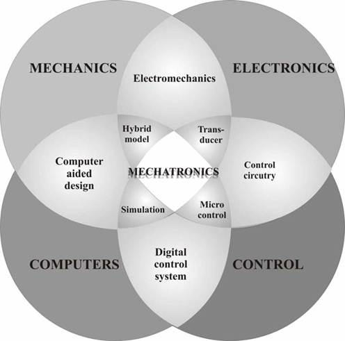
Figure 1a. Basic principle; Mechatronics circular-model.
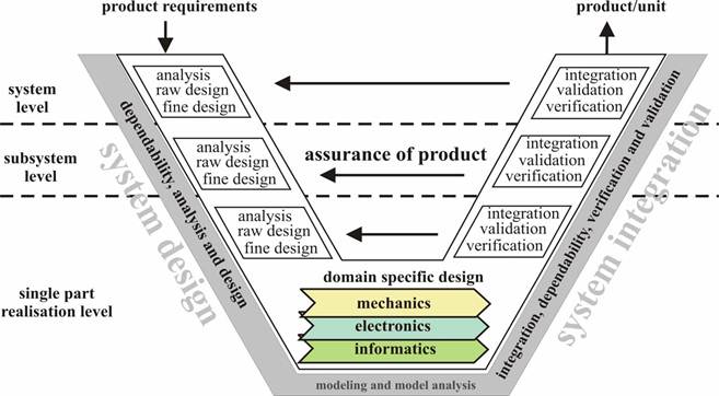
Figure 1b. Mechatronics design V- model, VDI 2206 2003 [3].
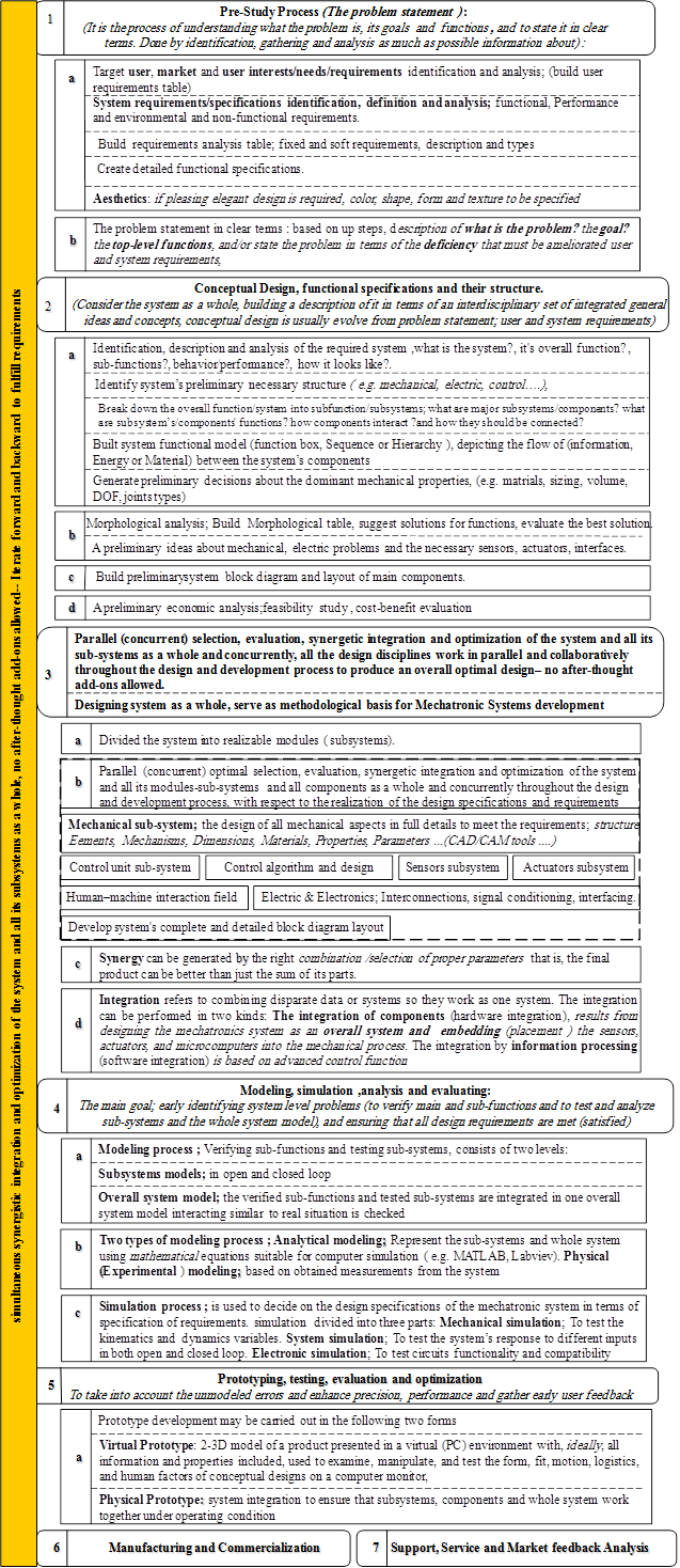
Figure 1c. Systematic Guideline steps for Mechatronics systems design education-oriented methodology.
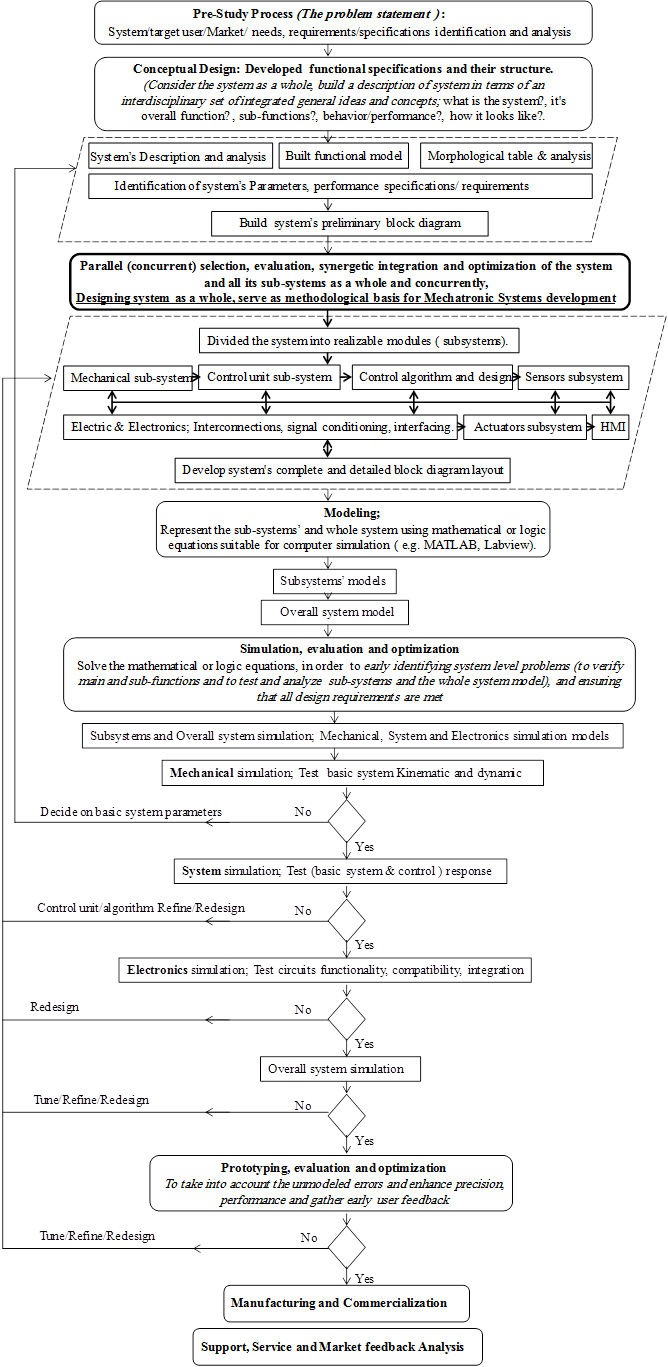
Figure 1d. Flowchart representation of proposed Mechatronics system design methodology.
Mechatronics system design: The design of Mechatronic systems can be facilitated using systems engineering design approach, Mechatronics system design is a modern interdisciplinary design procedure, it is the concurrent (instead of sequential) selection, evaluation, synergetic integration and optimization of the whole system and all its sub-systems and components as a whole and concurrently, all the design disciplines work in parallel and collaboratively throughout the design and development process to produce an overall optimal design– no after-thought add-ons allowed, this approach offers less constrains and shortened development, also allows the design engineers to provide feedback to each other about how their part of design is effect by others. here it is important to notice that the ideal process of concurrent (simultaneous) approach is characterized by parallel work of a potentially distributed community of designers that know about the parallel work of their colleagues and collaborate as necessary; sharing of knowledge in a common database builds a basis of cooperative design, since a shared database is the place where all design results are integrated [8]. Integration refers to combining disparate data or systems so they work as one system. The integration within a Mechatronics system can be performed in two kinds, a) through the integration of components (hardware integration) and b) through the integration by information processing (software integration) based on advanced control function. The integration of components results from designing the Mechatronics system as an overall system, and embedding the sensor, actuators, and microcomputers into the mechanical process, the microcomputers can be integrated with actuators, the process, or sensor or be arranged at several places. Integrated sensors and microcomputers lead to smart sensors, and integrated actuators and microcomputers developed into smart actuators. For large systems bus connections will replace the many cable. Hence, there are several possibilities to build up an integrated overall system by proper integration of the hardware. Synergy from the Greek word (synergeia) meaning "working together" and refers to the creation of a whole final products that is better than the simple sum of its parts, the principle of synergy in Mechatronics means, an integrated and concurrent design should result in a better product than one obtained through an uncoupled or sequential design [1, 5, 6]. The final product can be better than just the sum of its parts, synergy can be generated by the right combination of parameters.
3. Proposed Guideline for Mechatronics Systems Design Education Oriented Methodology
In the following, the proposed in [1] simple, clear, easy to memorize and follow design steps, shown in diagram Figure 2, are summarized, with emphasize on role, classification and selection criteria of each Mechatronic system's subsystem.
3.1. The Pre-study Process - Problem Statement
is a list and description of the problem(s), the problem statement is more important than problem solving, where before attempting to find a (design and built) solution for a given a problem, it is very important to understand what is the problem and to state it in clear terms; it is the process of gathering as much information as possible about the product, it's main function, subfunctions, it's future applications, functional/performance/environmental specifications analysis with respect to behaviour, quality, physical dimensions, costs, all possible conditions of operation and the environmental factors; analysis of target market, target user’s (Customer) needs/interests/requirements, aesthetics, resulting in a preliminary design specification, which has to be updated continuously according to the new information gathered during the development process.
3.2. Conceptual Design
In Mechatronics design approach, it is important to consider the system as a whole throughout the development process from the very start of the design process. Conceptual design is an early stage of design in which designers are building a description of the proposed system in terms of an interdisciplinary set of integrated general ideas and concepts, describing product and product's overall function, its most important sub-functions, that will be employed in solving a given design problem and their supporting analysis, generating solutions without detailed design parameters and decide how to interconnect these concepts into an appropriate system architecture. Conceptual design acts as a blueprint for the subsequent design and implementation stages [1, 7]. Conceptual design is usually evolve from problem statement user and system requirements.
3.2.1. Parallel (Concurrent / Simultaneous) Selection, Evaluation, Synergetic Integration and Optimization of the System and All Its Subsystems and Components as a Whole Concurrently
Mechatronics engineer is expected to design products with synergy and integration toward constrains like higher performance, speed, precision, efficiency, lower costs and functionality, also Mechatronics engineer must be skilled in modelling, simulation, analysis, and control of dynamic systems and understand the key issues in hardware implementation.
Since Mechatronic system consists of many different interconnected subsystems (components/elements), itcan be divided into realizable modules/subsystems/components, then the optimal selection, evaluation, synergetic integration, optimization of modules and all components, and the exchange of information between different modulesand models of different domains (e.g. MCAD, ECAD), is to be carried out in parallel and collaboratively with respect to the realization of the design specifications and requirements, to produce an overall optimal design. As shown in Figure 2a, b. the following main interconnected subsystems can be introduced; Mechanical subsystem, Control unit/Algorithm subsystem, Actuators subsystem, Sensors subsystem, Interconnection, signal conditioning, and interfacing subsystem, based on selection and synergetic integration of all subsystems, complete and detailed system block diagram layout is developed. It is highly important that during the design, changes in one subsystem and other subsystems be evaluated simultaneously.
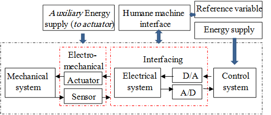
Figure 2a
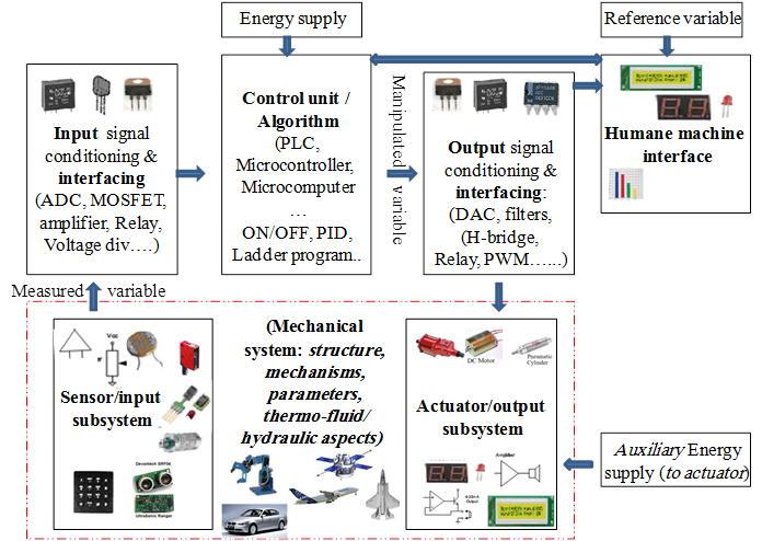
Figure 2b
Figure 2. Working principle and main subsystems of Mechatronic products.
3.2.2. Working Principles of Mechatronic Systems
Regardless of the type of Mechatronic system, and before approaching design, role, classification and selection criteria of its subsystems, there is a need to understand the fundamental working principles of Mechatronic systems. The general scheme, shown inFigure 2. The basis of many Mechatronic systems is the mechanical subsystem which is a power-producing/generating machine (mechanical aspects/elements, including; mechanical structure, mechanisms, their mechanical properties and parameters, thermo-fluid and hydraulic aspects of a Mechatronics system), which converts or transmits the mechanical process (by actuators). Information on the state of the mechanical process and environment has to be obtained by (using sensor for) measuring generalized flows (e.g. speed, mass flow) or electrical current/potentials (e.g. temperature, speed). Together with the reference variables, the measured variables are the inputs for an information flow, which the digital electronics (Control unit compares them, and according to control algorithm) convert into manipulated variables for the actuators (e.g. motors) to control and optimize the physical system and meeting specifications, or for monitored variables to display. The addition and integration of feedback information flow to a feed forward energy flow in the mechanical system (e.g. motor drive, drainage pump) is one of the characteristics of many Mechatronic systems. Interactions of man and machine have been profoundly enhanced by the development of electronics and IT technologies (e.g. SMS, voice control) and interactions have become more versatile and user-friendly. [9].
3.2.3. Mechanical Subsystems
The Mechanical subsystem design involves the design of all mechanical aspects in full details to meet the system requirement specifications, the design can be supported by software tools such as CAD/CAM.
Mechanical elements refer to mechanical structure, mechanisms, their mechanical properties and parameters, thermo-fluid and a hydraulic aspect of a Mechatronics system, an example on mechanical subsystem and its components is shown in Figure 3.
As noted, during the design of Mechatronic systems, it is important that changes in the mechanical structure and other subsystems be evaluated simultaneously; a badly designed mechanical system will never be able to give a good performance by adding a sophisticated controller, therefore, Mechatronic systems design requires that during an early stage of the design, the mechanical system, it's dynamics, with proper choice of mechanical properties needed to achieve a good performance and the control system structure, all to be designed as an integrated system, and correspondingly modelled and simulated to obtain unified model of all, that will simplify the analysis and prediction of whole system effects, performance, and generally to achieve a better performance, a more flexible system, or just reduce the cost of the system. as well as, advices related to control system issues such as positioning (placement) of sensors, actuators and control circuits.
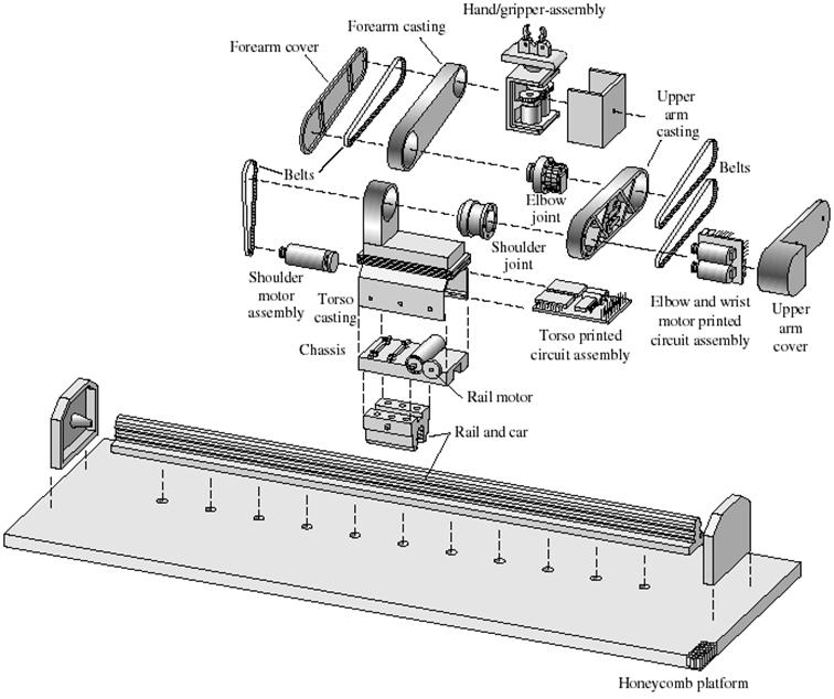
Figure 3. Example on Mechanical subsystem and components, ORCA robot showing the mechanical structure and components. [Hewlwtt-Pakard company, 1993].
3.2.4. Control Unit/Algorithm Role, Classification, Selection Criteria and Integration
Mechatronics systems are supposed to be designed with synergy and integration toward constrains like higher performance, speed, precision, efficiency, lower costs and functionality and operate with exceptional high levels of accuracy and speed despite adverse effects of system nonlinearities, uncertainties and disturbances. Therefore, Control is the core of Mechatronics system, and one of important decisions in Mechatronics system design process are, two directly related to each other subsystems, the control unit (physical-unit) and control algorithm subsystems selection, design and integration (see Figure 2). A variety of possible physical-control subsystem and algorithm options are shown in Figure 4. As shown, three components can be identified at this level; the control system, control algorithm and the electronic unit subsystems (signal conditioning-interfaces).
The control is the central and most important part (brain) of Mechatronic system, it commands, controls and optimizes the process and must ensure excellent steady-state and dynamic performance [1]. There are a number of possible physical-control subsystem options, including but not limited to: Personal computer (PC), Microcomputer, Microcontroller, Digital signal processors (DSP), Application specific integrated circuits (ASICs) and Programmable logic controller (PLC). Also, there are a variety of control algorithms: ON-OFF, continuous PID-modes, Feedforward, adaptive, intelligent (Fuzzy logic, Neural network, Expert Systems and Genetic) control algorithms [1].
The key factors that might influence the decision on selecting certain control unit and algorithm include; a) Operation (how system will run and how tasks/ instructions are processed), b) Robustness/environment (e.g. industrial, soft), c) Serviceability (availability of replacement components and ease of repair/ replacement over controller life), d) Security (e.g. viruses), e) programming: Both programming environment (how control executes program) and language (e.g. C++) affect machine development time and operation f) unit cost, cost of final product, precision, required time to market, g) Size-space saving, h) Integration with whole system, i) Processing power, also, h) safety criticality of the application, and number of products to be produced [1].
Control System Design; Based on particular Mechatronics system purpose, destination, desired performance, precision, efficiency, costs, functionality and complexity, the control unit/algorithm are selected and designed. The terms control system design can be referred to any of the following three forms; a) writing corresponding control algorithm/program (e.g. for PLC, CNC or Microcontroller) to control the process, or b) for intelligent control algorithms, developing a knowledge base, Inference mechanisms; and communication interfaces, or c) the process of selecting feedback gains (poles and zeros) that meet design specifications in a closed-loop control system. Most design methods are iterative, combining parameter selection with analysis, simulation, and insight into the dynamics of the plant [10, 11]. Different control system design approaches are available and can be applied to design and test the selected control algorithm [1]. In [12, 13] are presented simple and user friendly controllers and design guide that illustrate the basics of controllers and control algorithms, their elements, effects, selection and design procedures.
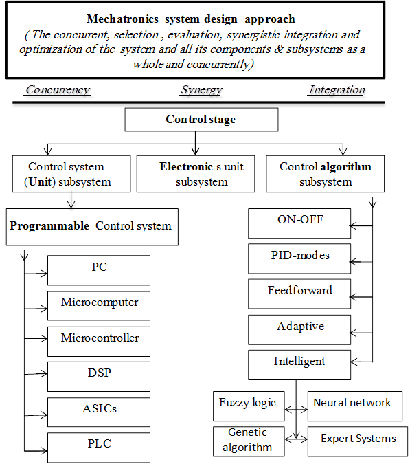
Figure 4a. Components at control stage; Control system / algorithm and electronic unit subsystems.
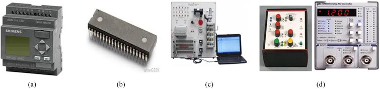
Figure 4b. Physical control unit options; a) PLC, b) Microcontroller, c) Computer, d) analog controllers.
3.2.5. Actuators Subsystem Role, Classification, Selection Criteria and Integration
Actuator converts an information signal from the control unit, into energy acting on the basic system, it is the hardware device that physically carry out the control actions, (the physical changes of the process), where it runs a certain kind of mechanical-dynamic load process, this can be a position, speed, acceleration, heat, pressure, flow, torque (force), power or a combination.
Classification: Actuators can be classified into the following general groups (Figure 5): a) Electric actuators e.g. diodes, power MOSFET, solid state relay, b) Electromechanical actuators e.g., AC and DC electrical motors, stepper motors and electromagnets, c) Electromagnetic actuators, that can be classified into two types; a) The magnetic forces acting at distance, that are classified into three types; 1) Moving coil actuator (solenoid type actuators relay, valves), 2) Moving magnet actuator, 3) Moving iron actuator, the second types of Electromagnetic actuators is 2) magnetically-controlled active materials; that are classified into two types; 1) Magnetostrictive, 2) Magneto Rheological Fluid Actuator, d) Fluid power actuators, e.g., hydraulics, pneumatics, e) Smart or unconventional actuators e.g., piezoelectric, magnetostrictive, memory metal micro and nana actuators drive joint. The new generations of actuators include smart material actuators, microactuators, and nanoactuators.
Selection criteria: The factors must be taken into consideration when selecting the type of actuator include; the integration with the whole system (e.g. available volume to integrate in whole system’s construction), Positioning accuracy, Speed range, dynamics and required behavior, Power requirement; AC or DC, Continuous power output; to meet both power and torque requirements, duty cycle; Continuous or intermittent, transmission, Environment, Control unit, Drive, Cost, Availability.
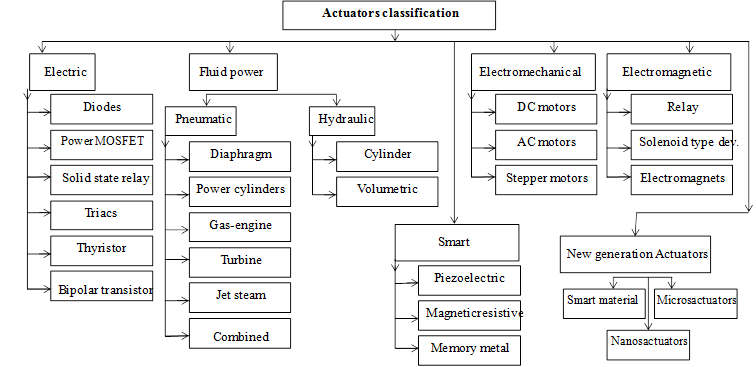
Figure 5. Actuators classifications and examples.
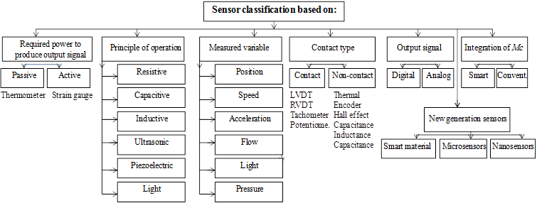
Figure 6. Sensors classifications and examples.
3.2.6. Sensors Subsystem Role, Classification, Selection Criteria and Integration
A sensor is a device that when exposed to a physical phenomenon (temperature, displacement, position, speed, force, pressure, level, etc.) produces a proportional output signal (electrical, mechanical, magnetic, etc.) [13]. The term transducer is often used synonymously with sensors. Therefore, the sensor measures (detects) a state variable, produces a proportional output signal, transducer converts it into an information signal and transmit it to the control unit. In Mechatronic systems, sensor subsystem can be as simple as a single sensor or can consist of additional components such as filters, amplifiers, modulators, and other signal conditioners.
Standard signals: Main two standard instruments' signals for controller to accept as inputs from sensors and outputs to actuators are; a) 0-20mA or 4-20mA current loops; current depends linearly on the measured variable's value, and are selected because of their immunity to noise and the distances that the signal can be transmitted, where current signals are less susceptible to degradation when transmitted over long distances, b) 0 to 10 volt, it is not commonly used in many control systems because this signal is susceptible to induced noise and the distance of the instrument or final control element is limited due to voltage drop.
Classifications: Sensors can be classified in different ways (shown in Figure 6): based on measured variable (e.g. Linear/Rotational sensors, Acceleration sensors, flow sensors), or based on the type of output signal (analog or digital), or based on the power required to produce the output passive or active, where active sensors require an external source of power (excitation voltage) to operate, that provides the majority of the output power of the signal, meanwhile passive simply detect and respond to some type of input from the physical environment, or based on principle of operation (e.g. resistive, capacitive, ultrasonic), or based on contact: as contact sensors (e.g Piezoelectric, strain gauge, LVDT) or non-contact sensors (e.g. Hall effect, capacitance), also Integration of sensors and microcomputers lead to smart sensors, where the signal from the sensor is digitized, then digital processing is performed by a microcontroller, followed by D/A conversion to produce the analog current signal, the new generation of sensors include smart material sensors, microsensors, and nanosensors.
Selection criteria: The quality of the whole system performance is, directly related to the performance of the sensor, therefore, when selecting sensor for measuring controlled variables in Mechatronics design, several characteristics become important, mainly: the integration with the whole system, the dynamics of the sensor, stability, range (Difference between the maximum and minimum value of the sensed parameter), resolution (The smallest change the sensor can differentiate), precision (Ability to reproduce repeatedly with a given accuracy), Response time (The time lag between the input and output), Operating temperature, Deadband, Sensitivity, Linearity, size, cost, and signal processing.
Choosing a sensor/actuator that satisfies all the above to the desired specification is difficult. As a solution a short list of sensors that satisfies most specifications, can be generated, and final selection will then depend on the following factors; size, extent of signal conditioning, reliability, maintainability and cost.
3.2.7. Interconnection, Signal Conditioning, and Interfacing, Selection and Integration
In Mechatronics system design, the selection of control unit, control algorithm, sensors and actuators is followed by selecting and integrating the electronic unit (Interconnection, signal conditioning, and interfacing) e.g. power supplies, drives circuits, signal processing-conditioning circuits and data acquisition systems). As shown in Figure 2, these are selected to interface the whole system components and match components specifications and ratings in and to optimize the system performance.
Since most measurement and control apparatus are of an analog nature, while control units are digital, to enable the control unit to communicate with the outside analog world, interface hardware allows analog/digital interfacing, communication of sensor signal to control unit and communication of control signal from the control unit to the actuator, also, Sometimes, this unit can fulfil additional tasks: system protection, display and setting of some functional parameters etc. For example, as shown in Figure 7a, the sensor output signal, before it can be fed to the controller, may have to be demodulated, amplified, filtered (remove unwanted signals), linearized, and isolated (e.g. isolating the transducer signals from the computer). Interconnections, signal conditioning, and interfacing components include; power supplies, drives circuits, signal processing-conditioning circuits, and data acquisition systems.
The drive is the link between the controller and actuator, the drive main job is to translate the low energy reference signals from the controller, (e.g. Microcontroller, PC, PLC), into high energy power signals to the actuator (e.g. motor).
Classifications: Generally, interconnection, signal conditioning, and interfacing can be classified into three basic types; a) Interfacing input devices, includes; discrete circuits, Filters, amplifiers, ADC/DAC, voltage divider circuit, Relay circuit, b) Interfacing output devices, includes; ADC/DAC, Amplifiers, power transistors drives Transistors/MOSFET circuit /Darlington-pair driver, Relay drive circuit, PWM. c) Advanced component Interfacing (digital display, LCD, touch screens, voice activation). A detailed classification is depicted in Figure 7c. To interface different input and output devices (e.g. DC motor, stepper motor, solenoid, relay, switches, LED, Counter module, LCD) to the control unit (microcontroller, PLC), exist standard interfacing circuits, including; a) The Transistor Interfacing Circuit, b) Using a Darlington Driver IC, c) The Relay Interfacing Circuit, d) The Power MOSFET Interfacing Circuit, these for interfacing to microcontroller, are shown in Figure 7b.
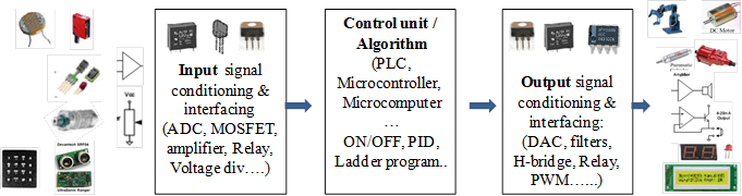
Figure 7a. Interconnection, signal conditioning, and interfacing.
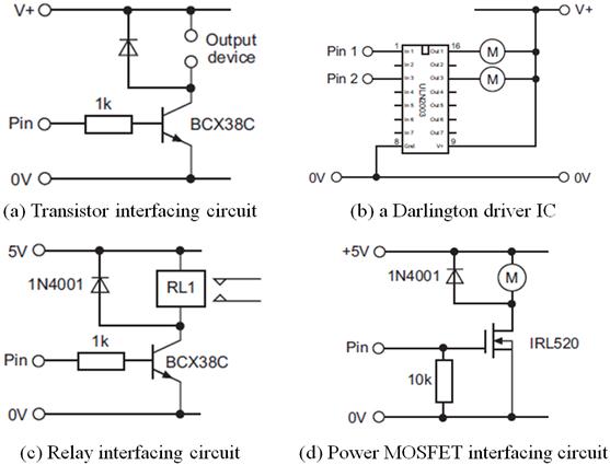
Figure 7b. Standard interfacing circuits to microcontroller [15].
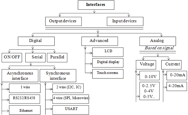
Figure 7c. Classification of interconnection, signal conditioning, and interfacing circuits.
The selection depends on the voltage/current (power) ratings of the input/output devices, characteristics, as well as, control unit selected.
Human–machine interaction field are Control of the machine, and feedback from the machine which aids the user (e.g operator, customer) in making operational decisions,: efficient, simple and easy to understand and use interface, enjoyable to operate a machine, simple input/ output means such as advanced component Interfacing (Selection and integration of) LEDs, digital display, LCD, touch screens, voice activation.
3.2.8. Develop Complete and Detailed System Block Diagram Layout
Based on overall system, sub-systems and components selection, design and integration, a complete and detailed system block diagram layout is developed, showing interconnections and interrelation and energy flow.
3.3. Modeling, Simulation, Analysis and Evaluation
The primary challenge in modelling Mechatronic systems lies in their multi-domain nature, consisting of many different interconnected, interdisciplinary, integrated subsystems (sensors, actuators, interfaces and mechanical geometry). The main goal of Modeling, simulation, analysis and evaluation in Mechatronics design are; early identifying system level problems (to verify sub-functions and test sub-systems), and ensuring that all design requirements are met.
In evaluating concepts, a modelling-simulation-and-analysis approach must replace any design-build-and-test approach. The modelling, simulation, analysis and evaluation processes in Mechatronics design consists of two levels; subsystems models (e.g. plant-dynamics, inertias, energy flow, gears, interfaces, sensors, actuators, control) and overall integrated system model with various sub-system models interacting similar to real situation, all engineering subsystems (e.g. mechanical, electrical and electronic components) should be included in overall system model. Once models are available, computer simulation is used to decide on the design specifications of the Mechatronic system based on the specification of requirements [14].
3.4. Prototyping, Testing, Evaluation and Optimization
There is no single model which can ever flawlessly reproduce reality, there will always be errors called as unmodeled errors between behaviour of a product model and the actual product. In order to take into account the unmodeled errors and enhance precision and performance in the design process, the Mechatronics design approach includes prototyping phase. After verifying the required system design through computer simulation, all components for the system can be acquired in order to assemble-integrate the required system, Considering that, Mechatronics system design execute the first prototype of machine in virtual system, not in physical prototype.
3.5. Manufacturing and Commercialization
Once the developed system is tested, refined, and confirmed, the processes of technology transfer to industry, and commercialization, could begin; Process planning (PP); product manufacturing plan, including the most appropriate sequence of individual processing and assembly operations needed to produce the product, selecting methods of production, tooling, fixtures, and machinery. Design for manufacturing and assembly (DFMA); the integration of product design and process planning into one common activity for ease of manufacturing of the collection of parts that will form the product after assembly and to reduce overall part production Material, Overhead, Labor cost. System acquisition (for purchased items), System implementation (Manufacturing) and required automation, Quality assurance and control, Packaging and marketing.
3.6. Support, Service and Market Feedback Analysis
The sustained success of products commercial and marketing depends on market feedback analysis and a comprehensive range of customer support and service. Market feedback analysis is to use of objective market data, customer satisfaction surveys, interviews, routine interactions and communications, product and service quality and reliability data, to give insight into customers' perspective and expectations of product modifications of design and performance.
4. Conclusions
Steps of education oriented Mechatronics system design methodology, are summarizes, with emphasize on role, classification and selection criteria of each Mechatronic system's subsystem. Main design terminologies and concepts are discussed and integrated in the design methodology.
References
- Farhan A. Salem, Ahmad A. Mahfouz Mechatronics Design and Implementation Education-Oriented Methodology; A Proposed Approach, Journal of Multidisciplinary Engineering Science and Technology Volume. 1, Issue. 03, October – 2014.
- Farhan A. Salem Ahmad A. Mahfouz’’ A Proposed Approach to Mechatronics Design and Implementation Education-Oriented Methodology ' Innovative Systems Design and Engineering, Vol. 4, No. 10, pp 12-29, 2013.
- Vasilije S. Vasić (2008), Mihailo P. Lazarević, Standard Industrial Guideline for Mechatronic Product Design, FME Transactions, 104, vol. 36, No 3,.
- Richard C. Dorf, Robert H. Bishop Modern Control Systems, Prentice Hall, 2011.
- Rolf Isermann (1996), Modeling and Design Methodology for Mechatronics Systems, IEE/SME transaction on Mechatronics, VOL. 1, No 1.
- De Silva, Clarence W. (2008), Mechatronics: An Integrated Approach, CRC Press, 2005
- A. Saleema (2011), T. Tutunji and L. Al-Sharif, Mechatronic system design course for undergraduate programmes,European Journal of Engineering Education,Vol. 36, No. 4, August 2011, 341–356.
- John Billingsley (2008), ''Essentials of Mechatronics'', John Wiley & Sons, 2006. Kenway Chen, Jitesh Panchal, Dirk Schaefer, an integrated approach to design mechatronics systems: cross-disciplinary constraint modeling'', ASME International Design Engineering Technical Conferences & Computers and Information in Engineering Conference, IDETC/CIE 2008, New York City.
- K. Crai g, F. Stolfi (2002), "Teaching control system design through Mechatronics: academic and industrial perspectives." Mechatronics, Vol 12, No. 2, pp. 371-381.
- D'AzzoJohn Joachim, Houpis, Constantine H, "Linear control system analysis and design: conventional and modern", 1988).
- Hedaya Alasooly, ''Control of DC motor using different control strategies'' global journal of technology and optimization, 2011.
- Farhan A. Salem, Controllers and Control Algorithms: Selection and Time Domain Design Techniques Applied in Mechatronics Systems Design (Review and Research) Part I, International Journal of Engineering Sciences, 2 (5) May 2013, Pages: 160-190
- Farhan A. Salem, PID Controllers and Algorithms: Selection and Design Techniques Applied in Mechatronics Systems Design - Part II, International Journal of Engineering Sciences, 2 (5) May 2013, Pages: 191-203.
- Robert H. Bishop, The Mechatronics handbook, II edition, Mechatronics systems sensors, and actuators, fundamentals and modeling, CRC press, 2008.
- Microcontroller interfacing circuits, Section 3, Revolution Education Ltd. Web: www.picaxe.co.uk Version 4.4 12/2010.


