
International Journal of Modern Physics and Applications, Vol. 2, No. 3, May 2016 Publish Date: Sep. 3, 2016 Pages: 15-17
A Magnetic Field Transducer Based on the Mechanoelectric Effect in Semiconductors
Sh. M. Aliev, I. K. Kamilov, K. M. Aliev, N. S. Abakarova, M. Sh. Aliev, Zh. G. Ibaev*
Institute of Physics, Daghestan Science Center, Russian Academy of Sciences, Makhachkala, Daghestan, Russia
Abstract
A sensitive magnetic field transducer based on the mechanoelectric effect in semiconductors is designed. The transducer is a magnetic dipole with the central axis of rotation, on poles of which are mounted side needles which can exert mechanical pressure on a fixed strain-sensing semiconductive elements. The I-V curves of the semiconductive elements lead to modification in the magnetic field. The I-V curves show that the reverse I-V branch is more sensitive to the magnetic field than the forward one. The sensitivity of the produced transducer is 3.0×10³ V/A×Oe.
Keywords
Magnetic Field, Magnetic Dipole, Semiconductor, p-n Junction, Current-Voltage Characteristic, Mechanoelectric Effect
Received:November 17, 2015
Accepted: May 19, 2016
Published online: September 3, 2016
@ 2016 The Authors. Published by American Institute of Science. This Open Access article is under the CC BY license. http://creativecommons.org/licenses/by/4.0/
1. Introduction
A change in current-voltage (I-V) characteristic of semiconductive elements under mechanical pressure, known as a mechanoelectric effect, is used for design of various pressure transdusers, microphones and accelerometers [1,2]. The p-n junctions, Schottky - barrier diodes and tunnel diodes are used as a strain-sensing element in the mechanoelectric converters [3-9], and the pressure is usually developed in a uniaxial regime. The physical reason of the mechanoelectric effect is the semiconductor energy level shift under the influence of the strain and the associated change in the spectrum of the current carriers–electrons and holes, depending on the strain [1,2]. Mechanoelectric transducers in base of semiconductor devices have highly attractive features. They provide the high sensibility of the transformation and a wide range of operating frequencies at small masses and sizes. Semiconductor mechanoelectric transducers prepared from germanium (Ge) and silicon (Si) are in most common use. Strain – sensing elements formed from these materials have a higher strain gauge factor which allows measuring small shares of strain [10,11]. In the semiconductor elements mechanical pressure can be originated by various ways. One of them is using of needle to transmit local pressure onto the semiconductor. In this case, even small external action follows by noticeable mechanical stretch. It should be noted, when the deformation generated in the semiconductor is great, the irreversible changes in the electrical characteristics of semiconductor are possible. Irreversible phenomena means that the current-voltage characteristic of semiconductor element does not returns to its initial form when stretch is removed. Irreversible phenomena occur in semiconductors when mechanical stretches are close to limit of elasticity [1]. So, as the mechanoelectric transducer is designed, it should be considered the force F applied to semiconductor element must be smaller than some critical value Fcr. In this case, the current-voltage characteristics of semiconductor elements are completely reversible [1]. Note, the critical force Fcr value depend on semiconductor material and on contact area of needle and semiconductor surface. This work reports the possibility to create a sensitive magnetic field transducer based on the mechanoelectric effect.
2. Design and Principle of Operation
Let's consider the magnetic dipole with central axis of rotation, on poles of which are mounted side needles which can mechanically press on fixed strain-sensing semiconductive elements (Fig. 1a). The torque will affect on this dipole if it is entered into the magnetic field H [12]:
![]() , (1)
, (1)
where M is the magnetic moments of dipole and a - the angle between H and M directions. The moment of forces always tends to turn the dipole towards the field, therefore, a direction of the force couple affecting on the dipole will depend on a mutual orientation of M and H vectors (Fig. 1 b and 1 c). Note that L=F×l and M=G×l, where F is the force acting on a dipole arm, l is the distance between dipole poles, G is the magnetic flux of the dipole pole [12]. For the pressure exerted by the needle on a semiconductive element, we get
![]() , (2)
, (2)
where C is a contacting area of the needle with a semiconductive element.
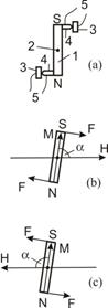
Fig. 1. (a) The schematic construction of the magnetic field transducer on the basis of mechanoelectric effect: (1) magnetic dipole; (2) axis of dipole rotation; (3) fixed strain-sensing semiconductive elements; (4) needles; (5) electric leads. (b, c) Schematic diagrams illustrating the force couple acting upon the magnetic dipole at mutually opposite directions of the magnetic field.
In the manufactured transducer was use the magnetic dipole with a length 15 mm and a cross-section 2´2 mm cut out from (CS-37 grade) samarium-cobalt permanent magnet. The dipole with indium coated tungsten needles fastened to poles was mounted on a clock pendulum mechanism. A needlepoint diameter was 60 mm. A germanium plates of 2×2 mm, with resistivity of 40 W×cm was used as semiconductive element. Ohmic contacts from Pb-Sb alloy were applied on one side of the plates. To improve of rectifier properties and creation of mechanically strong metal-semiconductor contact the several current pulses of 1A amplitude and a duration of 10 ms were passed through the diode. Finished transducer was placed into a plexiglass box to protect from dust and moisture of electric contacts and moving elements of the device.
Figure 2 shows the I-V curves of the transducer placed in the middle of solenoid. A magnetic field strength and its direction were controlled by fitting a value of the current passed through the solenoid and changing its direction, the angle a was 90°.
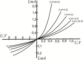
Fig. 2. Current-voltage characteristics of the transducer diodes in the magnetic fields of various strengths and directions: Н=0 (1); Н=5 Oe (2); Н=20 Oe (3); Н= –5 Oe (4); Н= –20 Oe (5).
As is seen from Fig. 2, a change in the magnetic field strength by a few (Oe) leads to a significant modification of the I-V curves of the point-contact diodes, and besides a change of the magnetic field in the reverse direction the I-V curve shifts to opposite side relative to I-V curve observed for H=0. This is explained by a change in the direction of force couple influencing on the dipole when changing the field direction (Fig. 1 b and 1 c). It should be noted, the current-voltage characteristic of point - contact diodes in Fig. 2 are completely reversible at repeat measurements.
The sensitivity of the transducer can be evaluated by the formula
![]() , (3)
, (3)
where DU=UH – U0 is the change of voltage on the diode when placing the transducer in magnetic field H and I is the current passing through the diode.
In a magnetic field with a strength of H=5 Oe, the transducer sensitivity was g=50 V/A×Oe for the forward I-V branch (I=0,4 mA) and g=3,0×10³ V/A×Oe for the reverse branch (I=0,1 mA), that is the reverse I-V branch is more sensible to the magnetic field than the forward one. In addition, the I-V curves show that the g-value depends on the magnetic field as well, being relatively more sensitive to weak fields. Particularly, described transducer can be apply to measure the direction and magnitude of the Earth’s magnetic field. The sensitivity of the transducer can be controlled toward both increase and decrease by varying the C and G parameter values entered into formula (2). However, it must be borne in mind that the upper measurable field is limited by the coercive force of the dipole, which must be considerably greater than the field strength to be measured. For this reason, the sensor dipoles should be made of high-coersivity magnetic materials.
3. Conclusions
In this paper, a sensitive magnetic field transducer based on the mechanoelectric effect in semiconductors is presented. Structurally the transducer is a magnetic dipole with the central axis of rotation, on poles of which are mounted side needles that can exert mechanical pressure on a fixed strain-sensing semiconductive element. Germanium plates of 2×2 mm and with resistivity of 40 W×cm was used as a strain-sensing elements. In order to improve the diode properties and provide for a high mechanical strength of the metal-semiconductor contact, the diode was subject to an electroforming treatment by passing current pulses with an amplitude of 1 A and a duration of 10 ms. A sensor was mounted at the centre of solenoid. The magnetic field strength and direction were controlled by changing the magnitude and direction of the current passed through the solenoid. It was shown, that a change in the field strength by a few Oersteds leads to significant modification of the I-V curves of the point diodes. Reversal change of the field direction shifts the I-V curve in the opposite direction relative to the curve observed for H=0. The I-V curves show that the transducer sensitivity depends on the magnetic field and being relatively more sensitive to weak fields and the reverse I-V branch is more sensitive to the magnetic field than the forward one. The sensitivity of the produced transducer is 3.0×10³ V/A×Oe.
References
- A.L. Polyakova, Deformation of Semiconductors and Semiconductor Devices, Izdatel’stvo "Energia", Moskow, 1979, P. 167.
- I.I. Krivonosov, Semiconductor Electroacoustic Converters in Radio Circuit, Izdatel’stvo "Energia", Moskow, 1977, P. 87.
- Y. Matukura, Japan. J. Appl. Phys. 4 (1965) 632.
- J.J. Wortman, J.R. Hansen, R.M. Burger, J. Appl. Phys. 35 (1964) 2122.
- J. Oda, Japan. J. Appl. Phys. 5 (1966) 113.
- H. Okamoto, H. Arigoshi, Y. Mizushima, Solid State Electronics 12 (1969) 441.
- N. Moza, S. Bermon, F.H. Pollak, Phys. Rev. Lett. 28 (1972) 225.
- W. Bernard, W. Rindner, H. Roth, J. Appl. Phys. 35 (1964) 1860.
- I.N. Kupenko, A.L. Polyakova, Physics and Technology of Semiconductors 10 (1976) 807.
- M.K. Bakhadyrkhanov, Kh. M. Iliev, Kh.F. Zikrillaev, Technical Physics Letters 22 (1998) 23.
- G.G. Babichev, S.I. Kozlovski, V.A. Romanov, N.N. Sharan, Technical Physics 10 (2000) 45.
- S. Chikazumi, Physics of Ferromagnetism, Izdatel’stvo "Mir", Moscow, 1987, P. 302.


