
International Journal of Modern Physics and Applications, Vol. 1, No. 4, September 2015 Publish Date: Aug. 3, 2015 Pages: 186-192
Numerical Modelling of Two-Phase Flow in an Effervescent Atomizer Using Volume of Fluid Mehtod
A. Helmy2, S. Wilson2, A. Siam2, A. Balabel1, *
1Mechanical Engineering Department, Faculty of Engineering, Taif University, Taif, Saudi Arabia
2Mechanical Power Engineering Department, Faculty of Engineering, Menoufiya University, Shebin El-Kom, Egypt
Abstract
Effervescent atomizers have showed to work well in terms of lower droplets size at relatively low injection pressure. In effervescent atomizer, a type of internal-mixing twin-fluid atomizer, the gas is bubbled in the liquid to form bubbly mixture upstream atomizer exit. The flow nature upstream atomizer exit affects the atomizer performance to great extent. In literature, several studies were done to simulate internal flow. Few results have used volume of fluid method. In the current study the two phase flow inside the atomizer was numerically simulated using the volume of fluid model. Validation with experimental work was performed first. The results were found in close agreement with the experimental correlation. The main purpose of the current study is to investigate the application of effervescent atomizer in aviation gas turbine and to investigate the internal flow evolution inside the atomizer. The fuel used is Jet-A1 commercial aviation fuel. The present results showed that the gas to liquid mass ratio (GLR) is one of the major contributory factors affecting the atomizer performance. The two phase flow was identified as slug flow in the discharge passage at low GLR (0.08%). The flow evolved to slug- annular flow at GLR= 0.5%. At high GLR (0.8%) the annular flow was distinguished. The mixing between phases was augmented with increasing GLR. Finally the liquid film thickness at the atomizer outlet was calculated. The results showed that the liquid film thickness decreased with increasing GLR. Lower GLRs affect liquid film thickness sharply than higher GLRs.
Keywords
Effervescent Atomizer, Liquid Film Thickness, Numerical Modelling, Two-Phase Flow, Volume of Fluid
Received: June 25, 2015
Accepted: July 22, 2015
Published online: August 2, 2015
@ 2015 The Authors. Published by American Institute of Science. This Open Access article is under the CC BY-NC license. http://creativecommons.org/licenses/by-nc/4.0/
1. Introduction
In the last decades, commercial aviation have raised as one of the most used transportation and has grown from a novelty to an essential. It enables people and goods to move around the globe in hours. The gas turbine engine, since its invention in 1940, emerged as the solution of extreme specific power requirement for aviation. The need for increased power led to the development of specialized aviation fuels. Nowadays, majority of commercial aviation gas turbine engines use Jet A1 fuel [1].
There is no doubt that the power generated by the gas turbine engine is affected by the combustion process which in turn is affected by the atomization process. Thus enhancement of fuel atomization, in terms of lower droplets size, will lead to better engine performance. From the various atomization techniques, Effervescent or Aerated-liquid atomization [2], type of internal mixing twin fluid atomizers, showed good atomization characteristics in terms of lower droplets size.
The basic idea of effervescent atomizer is by loading the bulk liquid with bubbles of the atomizing gas upstream of the atomizer exit to form two-phase bubbly mixture [2]. The bubbles explode just on exist of the atomizer which enhances liquid shattering and atomization. The presence of gas bubbles squeeze the liquid thickness, thus liquid velocity is increased, which augment the atomization [2].
Effervescent atomizer has several advantages such as; good atomization characteristics, in terms of smaller droplets size, relatively low injection pressures [2], small amount of atomizing gas, larger discharge orifices can be used reducing orifice clogging and erosion [2].
Effervescent atomizers can be used in many application fields [2], for instance; internal combustion engines, furnaces and burner, gas turbine engines, ram jet engines, pharmaceutical spray, fire suppression and spray coating applications.
The internal flow inside effervescent atomizer affects the atomizer performance and the corresponding produced spray to great extent. Lin et al [3] performed comprehensive experiments on the flow inside effervescent atomizer. The study embraced the variations of aerating tube configuration, converging angle connecting mixing chamber and discharge passage, discharge passage length and the effect of aeration levels. They concluded that the internal flow regimes have a great influence on the corresponding produced spray. The results showed the transition in internal flow structures from bubbly flow in the mixing chamber to slug flow in the final passage, to a co-annular flow as the aeration level increases. A correlation relating liquid film thickness in discharge passage with GLR was fitted.
Several numerical simulations were performed to investigate two-phase flow evolution inside effervescent atomizer. Tian [4] conducted a numerical simulation using mixture model to simulate the two-phase flow in effervescent atomizer based on the experimental work of Lin et al [3]. The model was tested for two different cases of GLRs and the results were compared with the experimental data. The results were somehow far from the experimental results of Lin et al [3]. This can be attributed to the 2-D geometry simplification adopted, which does not match with the actual atomizer geometry.
Esfarjani and Dolatabadi [5] used the Eulerian-Eulerian two-fluid model to simulate the three-dimensional structure of two-phase laminar flow inside the effervescent atomizer of the experimental of Lin et al [3]. The behaviour of liquid film in the discharge passage was investigated using different gas-to-liquid mass flow ratios (GLR), ranging from 0.08% to 1.25%. It was found that the liquid film thickness is slightly independent of liquid physical properties such as density and viscosity. The 3D Iso-surfaces of gas phase revealed that the gas flow is in the form of separated bubbles generated inside the mixing chamber, and evolved on their way toward the discharge passage. By increasing the aeration level, the flow structure near the nozzle exit will be changed from slug flow to co-annular flow. Mehmoud and Masud [6] investigated the use of the Volume of fluid (VOF) technique using ANSYS FLUENT to simulate the internal flow inside the effervescent atomizer used by Lin et al [3]. It was observed that at low GLR of 0.08% the gas phase in the mixing chamber can be identified as relatively large bubbles flowing in the liquid phase. The large bubbles evolve into large slugs of gas while entering the discharge duct. At higher GLR of 1.25%, sufficient gas-liquid mixing is achieved in the mixing chamber.
In the current study, the configuration used in the Air Force Research Laboratory (AFRL) [3] was modeled to numerically investigate the structures of the internal flow inside effervescent atomizer with Jet A1 commercial aviation fuel. Further, evolution of flow and the liquid film thickness in the discharge passage were investigated. The results for liquid film thickness in the discharge passage were further validated with experimental data available in the literature.
2. Governing Equations
The flow inside the atomizer was considered as isothermal flow. So only conservation of mass and momentum are required. For turbulence, the realizable k-ɛ model was selected, following the work of Mehmoud and Masud [6]. In addition, supplementary equation representing the volume of the two phases is incorporated in the volume of fluid model [7]. The equations for continuity, momentum and volume fraction, in compact form, are as follow;
![]() (1)
(1)
Where Sf represent the source term, f is general variable to be solved. The values of f, Sf and Gf are given in table (1) for each corresponding equation. The equation of turbulent kinetic energy and turbulent dissipation rate are described in more details in ANSYS FLUENT module [8]. For surface tension modelling, the continuum surface force model of Brackbil et al [9] was adopted. In this model, a balance between pressure drop across the surface, due to surface tension, and surface tension force is performed.
Table (1). Governing equations for the VOF model.
| Equation | |||
| Continuity | 1.0 | 0.0 | 0.0 |
| Momentum |
|
|
|
| volume fraction | α | 0.0 | 0.0 |
3. Geometry
The VI configuration used in the Air Force Research Laboratory (AFRL) by Lin et al [3] was modelled in the current simulation. The modelled effervescent atomizer has rectangular cross section. The atomizer dimensions are; mixing chamber with 6.4x2 mm cross section, converging angel of 50 degree, square discharge passage of 2x2 mm with length 40 mm and circular aerating tube with internal diameter of 760 µm and located at 25.4 mm upstream of the entrance of discharge passage.
In contrast with the previous studies and to account for the relevant physical phenomena such as vortex shedding, the atomizer geometry was extended to include the inlet section for length. The thickness of the aerating duct was calculated to be 350 µm. Therefore, 20 mm inlet section was modelled in addition to the mixing chamber and discharge passage.
Further, to simplify the geometry, the circular aerating tube was replaced with square duct with the equivalent cross section of 674x674 µm [6]. Figure (1) shows the 3-D isometric of the geometry.
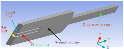
Figure 1. 3D isometric of the modelled atomizer.
4. Computational Domain and Boundary Conditions
Three dimensional simulations are essential to capture the asymmetric behaviour of the two-phase flow inside the atomizer. However, geometry symmetry a round (x-y) plane was assumed for simplification. Only one half of the domain was modelled [6], figure (1). Structured quad grids were used for meshing the atomizer. The total number of cells was around 600,000 cells. Further, the grids were clustered near the atomizer walls.
For inlet, velocity-inlet boundary condition was selected for both phases. The inlet velocity was calculated from the corresponding mass flow rate and the inlet cross section area. The value of the inlet volume fraction was given either 0 or 1 according to the dominant phase. For outlet, pressure outlet boundary condition with 1 atm was selected. Symmetry boundary condition was selected for symmetry plane as shown in figure (1). No-slip and stationary boundary condition was selected for all walls.
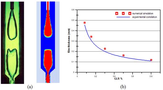
Figure 2. Comparison between simulation results and experimental work of Lin et al [3] for GLR=0.08% and QL=0.38 L/min.
5. Numerical Methodology
The finite volume approach was used to discretize the corresponding governing equations. The VOF explicit module in ANSYS FLUENT-15 [8] was selected for unsteady incompressible two-phase modelling. Pressure based solver was used. The first order implicit formulation was adopted for time discretization. The second order upwind scheme [8] was selected in momentum, turbulent kinetic energy and turbulent dissipation rate. For volume fraction equation, the Geo-Reconstruction method [8] was selected for accurate interface tracking. SIMPLE algorithm was used for pressure-velocity coupling. The enhanced wall function was selected for near wall treatment.
6. Results
6.1. Model Validation
The model was validated with the experimental work of Lin et al [3]. Figure (2-a) shows the numerical results of void fraction compared with the experimental photos of the internal flow for liquid flow rate of 0.38 L/min and GLR of 0.08%. The liquid film thickness calculated according to Esfarjani and Dolatabadi [5] was compared with the experimental correlation of Lin et al [3]. The area weighted void fraction was sampled with solution time and then averaged over time period of 5 millisecond. Figure (2-b) compares the calculated liquid film thickness and the experimental correlation of Lin et al [3]. It is clear that the current simulated film thickness compares well with the experimental measurement.
6.2. Jet A1 Results
The second step is to investigate using effervescent atomizer with Jet A1 aviation fuel. The evolution of internal two-phase flow and liquid film thickness are investigated. Table (2) summarizes the Jet-A1 properties [1] at temperature of 10 degree centigrade, to close the field-aviation conditions.
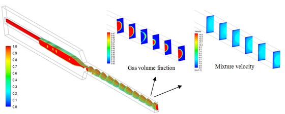
Figure 3. Gas volume fraction at time = 0.0654 sec and GLR=0.08%.
The volume flow rate of Jet A1 was kept constant at 0.38 L/min and the aerating gas was the air. The volume flow rate of the gas was varied to obtain the required GLR. The GLRs range and the corresponding flow rates and velocities for both Jet-A1 fuel and gas are tabulated in table (3). The upper limit of GLR is 0.8%. This upper limit was constrained by the compressibility effect relevant with high gas velocities. The calculations were performed with variable time step ranging from 3 µ sec to 1 n sec. the variable time step was selected to maintain a 0.25 courant number, for realistic simulations and accurate interface tracking.
Table (2). Jet-A1 and air velocities and mass flow rates at different GLRs.
| GLR (%) | Jet A1 mass flow rate (kg/s) | Jet A1 velocity (m/s) | Air mass flow rate (kg/s) | air velocity (m/s) |
| 0.08 | 5.19 E-3 | 0.58 | 4.13 E-6 | 7.43 |
| 0.15 | 5.19 E-3 | 0.58 | 7.74E-6 | 13.93 |
| 0.30 | 5.19 E-3 | 0.58 | 1.55E-5 | 27.86 |
| 0.50 | 5.19 E-3 | 0.58 | 2.58E-5 | 46.44 |
| 0.80 | 5.19 E-3 | 0.58 | 4.13E-5 | 74.31 |
Figure (3) shows the gas fraction volume for GLR of 0.08%. At this low GLR, the gas flows in the mixing chamber without any disintegration, this can be attributed to the separation zone behind the aerating tube. At this zone the surface tension dominates over the low drag force. At the discharge passage inlet, the liquid velocity is increased due to the converging part. The increased velocity shatters the intact gas jet into gas slugs at discharge passage inlet. These gas slugs are trapped by liquid flow in between. So the flow can be identified as gas slugs. In agreement with the work of Ramamurthi et al [10], it can be noticed that the slugs are elongated on their way to the exit, due to the high shear and pressure reduction.
Table (3). Properties of Jet A-1 aviation fuel.
| Density (kg/m³) | 820 |
| Viscosity (kg/m.s)x10-3 | 1.0254 |
| Surface tension (N/m)x10-3 | 23.8 |
Figure (3) also shows the contour of gas volume fraction at several planes upstream outlet and at atomizer exit. These planes are located at distances 0, 3, 6, 9, 12 and 15 mm from the atomizer exit. It can be noticed that the gas slugs are further surrounded by liquid. The nature of slug flow is obvious. Intermittent spray was reported at slug flow regime in discharge passage.
Figure (3), right, shows the mixture velocity upstream the exit plane. One can observe that the majority of mixture momentum is centred in the core region. The mixing between the two phases is slightly low at this aeration level. The gas is concentrated in the core and the liquid surround the gas flow, as the gas flow has not enough energy to disperse throughout the liquid flow.
With increasing GLR to 0.5%, the aeration level is increased and the gas flow has significant energy to disperse into the liquid stream. Figure (4) shows the gas fraction volume rendering at GLR 0.5%. One can observe from figure (4) that the gases flow in the mixing chamber as large lumps. These gas lumps have enough energy to disturb the liquid stream and pushing the liquid toward the mixing chamber walls. The gas occupy significant portion in the mixing chamber.
Towards the discharge inlet, the gas phase is evolved and the gas lump breaks up into larger gas slugs. These gas slugs are further coalescence in their way to the discharge passage outlet. Continuous gas stream is formed near the atomizer outlet. Mixing between the phases is augmented due to the high gas velocity, that the gas reaches the atomizer walls. The liquid is further squeezed towards the atomizer walls. The majority of mixture of momentum is still centered at the core region, as indicated from the mixture velocity contours shown in figure (4)-right. The effect of the vortex shedding phenomenon on gas flow is significantly obvious at this aeration level. Figure (5) presents the evolution of the vortex shedding phenomenon with simulation time. The wavy gas-liquid interface can be identified near the aerating tube tip.
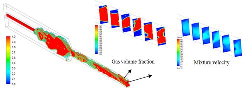
Figure 4. Gas volume fraction at time = 0.0307 sec and GLR=0.5%.
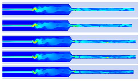
Figure 5. Vortex shedding phenomenon for simulation period of 1 millisecond at GLR 0.5% contours of mixture turbulent intensity at symmetry plane.
Further increase in GLR to 0.8%, increase the potential of the gas to disperse into the liquid. Instead of gas lumps generated for lower GLR, the gas occupy the majority of the mixing chamber, due to the increased gas flow. Figure (6) presents the evolution of the gas liquid flow inside the atomizer with simulation time for GLR 0.8%. The large gas quantity existed in the mixing chamber push and squeeze the liquid towards the chamber wall. The gas flow disturb the liquid stream. The available area for liquid flow is significantly decreased, which increase the liquid velocity. This causes the two phases to exhibit excessive shear at the interface. In the discharge passage, the gas flow as a continuous stream in the middle of the passage to form annular flow. It is noticeable from Figure (6) that the gas flow is surrounded by thin liquid film attached to the atomizer wall. Figure (6) also shows that majority of flow area is occupied by the gas. The gas also reaches the atomizer walls, due to the high gas flow rate. Majority of the flow area is occupied by gas at high velocity. So mixture momentum is no longer centred in the core region as the case for low GLRs. Figure (6) presents the contours of mixture velocity upstream and at atomizer outlet, it clear that the mixture momentum is not centred at passage core.
The mixing between the two phases is augmented at this high aeration level. Gas bubbles can be found in liquid film and liquid droplet can be identified in the annular gas flow, Figure (7). The turbulent intensity is shown in Figure (8). The effect of vortex shedding on the gas flow is obvious.
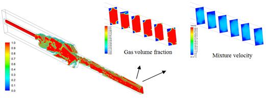
Figure 6. Gas volume fraction at time = 0.0193 sec and GLR=0.8%.
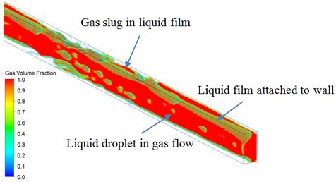
Figure 7. Gas volume fraction upstream atomizer exit at GLR 0.8% and time 0.0193 sec
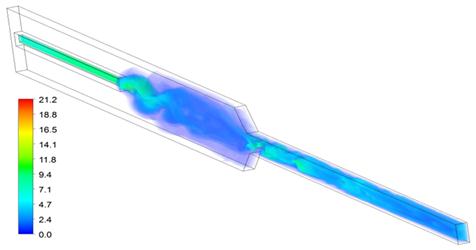
Figure 8. Mixture turbulence intensity at GLR 0.8% and time 0.0193 sec
Figure (9) shows the film thickness calculated according to the technique developed by Esfarjani and Dolatabadi [8].
At low GLR, the liquid film thickness changes rapidly. This may be attributed to the change in flow nature from bubbly to slug flow and finally to annular flow. At high GLR, no sharp change in GLR can be identified. This may be due to the dominant annular flow nature at high GLRs.
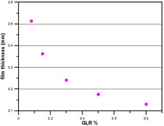
Figure 9. Liquid film thickness with GLR.
7. Conclusion
In the current study, structure of internal two-phase flow inside effervescent atomizer was studied numerically. Three dimension simulations were performed using the volume of fluid model. The main purpose of simulation is to investigate the evolution of the internal flow inside effervescent atomizer with aviation Jet-A1 fuel. Validation with experimental measurement was performed and the results compared well. The liquid film thickness was also calculated with statistical averaging. The results assured that the GLR is the major contributory factor in effervescent atomizers. At low GLR (0.08%) slug flow was identified. Increasing GLR to 0.5% evolved the flow to slug-annular. For 0.8% GLR annular flow was identified. The mixing between the two phases was augmented at higher GLRs. Results also showed that liquid film thickness decreased with increasing GLRs. The decrease in liquid film thickness at high GLR was less than at low GLR. The results showed the accuracy of volume of fluid method in predicting the interface between the two phases. The results also unveiled the superiority of effervescent atomizer on handling Jet-A1 fuel, that the liquid was squeezed to thin film at relatively low GLR which will augment the atomization process. Still complete simulation of the external spray is required to full investigation.
References
- "Aviation Fuel Properties", coordinating research council, Georgia, 1983. Sovani, S.D., Sojka, P.E. and Arthur H. Lefebvre, "Effervescent Atomization Prog. Energy Combust. Sci., Vol. 27, pp. 483-521, 2001.
- Sovani, S.D., Sojka, P.E. and Lefebvre, A.H. "Effervescent Atomization", Prog. Energy Combust. Sci., Vol. 27, pp. 483-521, 2001.
- Lin, K.C., Kennedy, P.J. and Jackson and T.A. "Structures of Internal Flow and the Corresponding Spray for Aerated-Liquid Injectors", AIAA Paper 2001-3569, 2001
- T. A., "Numerical Simulation of Transient Two-Phase Flow within Aerated-Liquid Injectors", AIAA Paper 2003-4266, 2003.
- Esfarjani S A, and Dolatabadi A, " A 3D simulation of two-phase flow in an effervescent atomizer for suspension plasma spray", Surf Coatings Tech, 2009, 203: 2074–2008.
- K. Mehmood and J. Masud," Analysis of Two-Phase Flow in an Effervescent Atomizer Using Volume of Fluid Method", AIAA paper, 0312, 2012.
- C.W. Hirts and B.D. Nicholas, "Volume of fluid (VOF) method for the dynamic of free boundaries", journal of computational physics, 39,201-255, 1981.
- FLUENT, Computational Fluid Dynamics Software Package, Ver. 6.3.26, Fluent Inc, Lebanon, NH.
- J.U. Brackbill, D.B .Kothe and Zemach, "A Contin-mium method for modeling surface tension", journal of computational physics, 100,335-354, 1992.
- K. Ramamurthi, U.K. Sarker, and B.N. Raghunandam "performance characteristics of effervescent atomizers in different flow regimes", atomization and spray, vol 19, pp 41-56, 2009.


