International Journal of Modern Physics and Applications, Vol. 1, No. 4, September 2015 Publish Date: Jul. 23, 2015 Pages: 169-174
Diamagnetism of Longitudinal Autosoliton in p-InSb in Longitudinal Magnetic Field
I. K. Kamilov, A. A. Stepurenko*, A. E. Gummetov
Dagestan Institute of Physics after Amirkhanov, Dagestan Scientific Center of the Russian Academy of Sciences, Makhachkala, Russia
Abstract
A longitudinal thermal-diffusion autosoliton generated in the non-equilibrium electron-hole plasma in p-InSb is shown to be diamagnetic in an external longitudinal magnetic field. The phenomenological estimate of the question allows deriving an expression for the magnetization, magnetic induction, and diamagnetic susceptibility of the autosoliton under an external magnetic field. Plots for these expressions, and computations and numerical estimations of the diamagnetism are performed.
Keywords
Autosoliton, Semiconductors, Non-Equilibrium, Dissipative Structure, Oscillations, Electron-Hole Plasma, Diamagnetism, Magnetic Field
Received: June 2, 2015
Accepted: June 13, 2015
Published online: July 23, 2015
@ 2015 The Authors. Published by American Institute of Science. This Open Access article is under the CC BY-NC license. http://creativecommons.org/licenses/by-nc/4.0/
1. Introduction
It is known [1] that all materials are magnetic. Their huge variety occurs in nature. A main contribution into the magnetism is made by electrons revealing intrinsic resultant magnetic moments – spin, orbital. In an external magnetic field, spin magnetic moments are oriented in the direction of the field generating a paramagnetic magnetization, while orbital magnetic moments are directed against the field creating a diamagnetic magnetization. As for InSb, it can be referred to weakly magnetic materials.
Cr-compensated InSb-samples with carrier concentrations of p ~ 1012 cm3 measured under a strong electric field [2,3] exhibit a consistently high conductance triggered by autosolitons (AS) formed in a non-equilibrium and excited electron-hole plasma (EHP) generated by the joule heating in the electric field. AS is a steady isolated intrinsic stable state of a system, in our case, of non-equilibrium carriers in semiconductors and semiconducting structures. In other words, AS is localized areas of extreme carriers concentrations and their temperatures. The EHP generated by the impact ionization, injection or traveling Gunn domain in GaAs thin films stratifies for current filaments and domains of electric field [4,5,6,7]; longitudinal ASs are found in n-Ge in EHP photogenerated, warmed by the electric field [8]; space-time structures in the form of static and pulsing current filaments in p-i-n diodes are studied in works [9,10]. The longitudinal autosoliton – the current filament implemented in p-InSb – we are interested in is a microlocalized region of enhanced carriers concentration and lower temperature (a cold AS) [11]. The estimation of autosoliton carriers concentration nAS in studied samples gives a value of nAS~1018 cm-3, while the initial specific carriers concentration in the sample is n = 1012 cm-3. Facts pointed out allow to consider that the conductivity and all electrical physical properties of the sample may be substituted by AS and its behavior under an external influence.
2. Review Experimental Results
Due to the fact that in the cold AS [11], the carrier concentration is higher in the center than in the periphery, a diffusional outflow from AS center to the periphery happens. Since the electron mobility considerably exceeds the hole mobility µе ≈ 100µр [12] the diffusional flow of electrons from AS center to the periphery will occur and a region along an AS central axis will be hole-rich. In an external longitudinal magnetic field, the electrons of this flow will start to rotate in spiral around the hole-enriched central area and simultaneously the electrons are involved in an ambipolar drift together with holes in the electric field applied to the sample.
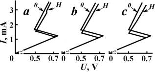
Fig. 1. Dynamic voltage-current characteristics of p-InSb at constant values of the applied longitudinal magnetic field: a – H1 = 2.4 104 A/m, b – H2 = 3.7 ·104 A/m, с – H3 = 6.2 104 A/m.
If we regard each turn of the spiral as an electron orbit around the positively charged center we could liken the indicated orbit to the electron orbit in atom. All orbits in AS in the longitudinal magnetic field are parallel to each other; lie in a plane perpendicular to the current and magnetic field directions. Possessing the orbital magnetic moment the turns define a total magnetic moment of the AS MAS. Summing up, we can conclude that the longitudinal AS becomes a diamagnet in the external longitudinal magnetic field. The experimental investigations on a behavior of AS current in Cr-compensated p-InSb under the longitudinal magnetic field show the voltage-current characteristics exhibiting the formation of AS and a change in the current with increase in the electric field to be different from the voltage-current characteristics (VCC) obtained at the external longitudinal magnetic field (Fig. 1). The AS current change in the magnetic field occurs at lower values than in the absence of that. When increasing the magnetic field, the difference of the current change on VCC rises. As is evident from Fig.1, a change in the sample conductivity in the longitudinal magnetic field does not occur in the ohmic region, i.e. when the AS lacks. In the case of AS presence (the non-linear region of VCC), the change of the sample conductivity or the AS current under the longitudinal magnetic field is associated with a change either in AS carriers concentration or in carriers mobility. A decrease in the longitudinal current with the increase of the longitudinal magnetic field is caused, on the one hand, by a fall in the mobility because of the path curvature of radially moving electrons, on the other hand, by a decrease in the mobility in accordance with µ ~ 1/n for a densifying initial plasma as a result of the current filament compression in the longitudinal magnetic field. And the carrier concentration in AS remains unaltered, but the specific concentration of carriers in AS changes due to the variation of an AS transversal size.
Work [13] reported that the longitudinal AS implemented in p-InSb can move in the Lorentz force direction at application of transversal magnetic field to the sample. Works [14,15] reported that the longitudinal AS formed in the non-equilibrium EHP in p-InSb moves in the direction of the sample periphery under the influence of the transversal magnetic field. On the other hand, it is experimentally shown [16] that the flow of the current filament in samples realized in the transversal magnetic field with a simultaneous effect of the longitudinal magnetic field fails. Put it in other words, the galvanomagnetic Ettingshausen effect appeared in the longitudinal AS in the longitudinal magnetic field inducing a AS flow in the sample is entirely blocked by the diamagnetism occurred in AS in the external longitudinal magnetic field.
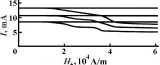
Fig. 2. Gauss-ampere characteristics for different currents of the longitudinal AS under the transversal magnetic field in the absence and presence of the longitudinal magnetic field ![]() || = 7.2 104 A/m = const.
|| = 7.2 104 A/m = const.
Fig. 2 exhibits dependences of three different currents of the longitudinal AS on the transversal magnetic field H⊥ (Gauss ampere characteristics – GAC) with the longitudinal magnetic field (straight lines) and without that (curve lines).
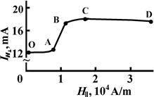
Fig. 3. Dependence of the longitudinal AS current under transversal magnetic field IH⊥ on the longitudinal magnetic field Н||.
As is evident from Fig. 2, the longitudinal AS current in the transversal magnetic field does not vary at a simultaneous effect of the constant longitudinal magnetic field. In the absence of the longitudinal magnetic field, the influence of the transversal magnetic field on the longitudinal AS current is essential [14,16].
Fig. 3 demonstrates the dependence of AS current in the specified transversal magnetic field IH⊥ (H⊥ = const) with a change in a longitudinal magnetic field value GAC. As is evident from Fig. 3, when increasing the longitudinal magnetic field the IH⊥ smoothly rises (OA segment) first and then abruptly jumps (AB segment) with a following transition for saturation or even decreasing (CD segment). The OA segment indicates a linear slowing-down in the AS flow in the transversal magnetic field. The AB segment – the abrupt positive jump of the current – testifies to a sharp slowing-down and a failure of the current filament flow. The BD segment shows a change in the AS current to be occurred only under the longitudinal magnetic field though the transversal magnetic field presents.
The observed effect is implemented due to simultaneous realization of two phenomena considered in works [13,14,17]. As works [13,14] depict, the current filament gains a temperature gradient in the Lorentz force direction under the influence of the transversal magnetic field by reason of the Ettingshausen effect. It is this temperature gradient that provides the transfer of the AS in the direction of the sample periphery characterized by a low temperature. In the dependence of transversal dimensions of the sample the AS achieves a sample boundary or such a temperature region where the longitudinal AS vanishes. It is experimentally observed a sharp decrease in the current or the instability of the longitudinal AS. On the other hand, in the longitudinal magnetic field, the longitudinal AS becomes a diamagnet, i.e. it is a cylinder consisting of electron path spirals moving around the hole-enriched region generating a self-magnetic field [17]. Spinning electrons are able to the heat transport from a hot current filament to a cold one. The higher the longitudinal magnetic field is, the faster the electrons spin, and the greater the heat transport is. Consequently, the temperature gradient difference of current filament fronts provided the flow of current is smoothed, what causes the slowing of the filament. The temperature gradient in the current filament disappears at a certain sufficient value of the longitudinal magnetic field and, consequently, the current filament fails to drift though the same transversal magnetic field presents. So, the Ettingshausen effect is blocked by the longitudinal magnetic field.
3. Phenomenological Consider, Results and Discussion
It can be suggested the longitudinal AS will change into the diamagnet in the longitudinal magnetic field of a minimum value H0 when the cyclotron radius r of electron spinning diffusing in the transversal direction with respect to the hole-rich region will be equal to an electron diffusion length Le, i.e. r = Le = meυd ![]() µ0eH0, υd = 2πLe
µ0eH0, υd = 2πLe ![]() τе. We obtain τе = 2πme
τе. We obtain τе = 2πme![]() µ0eH0, f = µ0eH0
µ0eH0, f = µ0eH0![]() 2πme, where υd is the electron diffusive drift rate, τе is the time of electron one turn in an orbit or the electron lifetime, f is the rate of electron orbital rotation, µ0 is the magnetic permeability of the vacuum. When a value of the longitudinal magnetic field is H0 = 2πme
2πme, where υd is the electron diffusive drift rate, τе is the time of electron one turn in an orbit or the electron lifetime, f is the rate of electron orbital rotation, µ0 is the magnetic permeability of the vacuum. When a value of the longitudinal magnetic field is H0 = 2πme![]() µ0eτе, the longitudinal AS is a cylinder consisting of electron path spirals spinning around the hole-enriched region generating a self-magnetic field. Fig. 4 presents the oscillograms of dependences differing by initial values of AS currents from the longitudinal magnetic field applied to the sample as triangular impulse – the dynamic GAC. The determination of a minimum magnetic field H0 at which the AS is changed into the diamagnet is the goal of the creation of such GAC. Measurements made using this and other methods provide the value of the magnetic field H0 ≈ 2000 A/m. We obtain the value of AS electron lifetime t = 2πme
µ0eτе, the longitudinal AS is a cylinder consisting of electron path spirals spinning around the hole-enriched region generating a self-magnetic field. Fig. 4 presents the oscillograms of dependences differing by initial values of AS currents from the longitudinal magnetic field applied to the sample as triangular impulse – the dynamic GAC. The determination of a minimum magnetic field H0 at which the AS is changed into the diamagnet is the goal of the creation of such GAC. Measurements made using this and other methods provide the value of the magnetic field H0 ≈ 2000 A/m. We obtain the value of AS electron lifetime t = 2πme![]() µ0eH0 from known expression for τе= 4.3 ∙ 10-10 s. This value is close to the results obtained in [12]. Let`s consider each spiral turn as the orbit of electron motion in the atom. All orbits are mutually parallel and perpendicular to the direction of the external magnetic field. Possessing the magnetic moment Mе the turns define the total magnetic moment of AS.
µ0eH0 from known expression for τе= 4.3 ∙ 10-10 s. This value is close to the results obtained in [12]. Let`s consider each spiral turn as the orbit of electron motion in the atom. All orbits are mutually parallel and perpendicular to the direction of the external magnetic field. Possessing the magnetic moment Mе the turns define the total magnetic moment of AS.
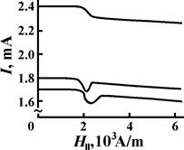
Fig. 4. Gauss-ampere characteristics for different currents of the longitudinal AS under the longitudinal magnetic field.
MAS = ΣnMn = nMe, where Me is the magnetic moment of a turn, n is the number of turns. The magnetic moment of an electron spinning around the hole with the rate f will be: Me = – IeS = – ef S, where S = πLe2 is the area of an electron turn.
Me = – µ0e2Le2H0![]() 2me (1)
2me (1)
The magnetic moment direction of a turn generated by the spinning of radially moving electron in the AS under the external longitudinal magnetic field is shown in Fig. 5. When the direction of the external magnetic field is such as shown in Fig. 5a, the Lorentz force, in accordance with the left-hand rule, is directed in such a way that a circular current triggered by the electron rotation flows in a clockwise order, what, in compliance with the right-hand screw, provokes the appearance of the magnetic moment oppositely directed to the external magnetic field. A change in the direction of the external magnetic field H0 into the opposite (Fig. 5b) entails the variation of the turn magnetic moment. So, the directions of induced magnetic moment Me in AS and the external magnetic field, as could be expected, are oppositely directed.
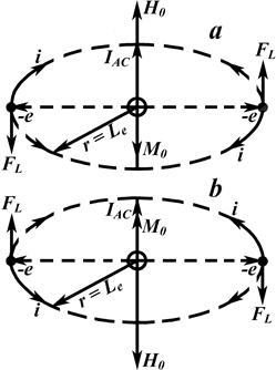
Fig. 5. The appearance of the diamagnetism in the longitudinal AS under external longitudinal magnetic field H0.
Radii of spinning electrons will be 0 ≤ r ≤ Lе by virtue of the spread of diffusing electron directions. Let`s change this inequality with the concept of the average radius of spinning electrons. We consider an AS cell with sizes as follows: a cell radius is r = Lе, a cell height is h = Le. The volume of the cell is νc = πLe3. The number of electrons in the cell is nс = neν = πLe3ne, ne is the specific concentration of electrons in AS. The unit radius of a spinning electron in this cell is rk = Lеcosαk, where αk is the angle between the diffusing electron direction and the plane perpendicular to the AS current direction. The number of turns k can be taken as the number of electrons since we allow for only the number of electrons irrespective of the orbit number, i.e. k = ne. αk = m(π![]() 2 k), where m is a direction number from 0 to k,
2 k), where m is a direction number from 0 to k, ![]() (π
(π![]() 2 k) = π
2 k) = π ![]() 2. Averaged radius is
2. Averaged radius is ![]() =
=![]() k
k![]() k = Lе
k = Lе ![]() (π
(π![]() 2k)]
2k)]![]() k. Numerical calculations
k. Numerical calculations ![]() (π
(π![]() 2k)]
2k)]![]() k yield a value of 0.637, whence it follows
k yield a value of 0.637, whence it follows ![]() 0,637Lе. The magnetic moment of spinning electrons for the considered cell is Mc = Menc = – (µ0e2
0,637Lе. The magnetic moment of spinning electrons for the considered cell is Mc = Menc = – (µ0e2![]() 2H0
2H0![]() 2me)∙πLe3ne = – 0.2πµ0e2Le5ne H0
2me)∙πLe3ne = – 0.2πµ0e2Le5ne H0![]() me. The magnetic moment of spinning electrons for all AS is:
me. The magnetic moment of spinning electrons for all AS is:
![]() – 0.2πµ0e2Le4lne H0
– 0.2πµ0e2Le4lne H0 ![]() mе (2)
mе (2)
A magnetization J0 of AS gets:
J0![]() ν =
ν = ![]() πLe2l = – 0.2µ0e2Le2ne H0
πLe2l = – 0.2µ0e2Le2ne H0 ![]() mе = – 0.2αH0 , (3)
mе = – 0.2αH0 , (3)
Where α = µ0e2Le2nе ![]() mе
mе
A magnetic induction of AS becomes:
B0 = H0 + J0 = (1 – 0.2α)H0 (4)
Let`s take 1 – 0.2α = µАS, where µАS is the magnetic permeability of AS.
We write B0 = µАS ∙H0.
An additional diamagnetic moment of electrons appeared at the application of the external magnetic field to spinning electrons is [18]:
Med = – µ0e2r2B0![]() 4mе (5)
4mе (5)
In case of H = H0 r = Le. However, the spinning electron radii are rk = Lеcosαk because of the spread of diffusing electron directions. Since the angular rate variation of the electron turn in the orbit is similar for all electrons irrespective of their orbit radii and linear travel we can employ the concept of the averaged radius. Following the preceding reasoning and allowing for the unit cell with a height of h = Lе, a square of S = πLe2, we change rk into the averaged radius ![]() 0,637 Lе. We yield: Mcd = – 0.4µ0e2Le2ncB0
0,637 Lе. We yield: Mcd = – 0.4µ0e2Le2ncB0 ![]() 4mе = (– 0.4µ0e2Le2B0
4mе = (– 0.4µ0e2Le2B0 ![]() 4mе ) πLe3ne= – 0.1πµ0e2ne Le5B0
4mе ) πLe3ne= – 0.1πµ0e2ne Le5B0 ![]() mе. The diamagnetic moment of spinning electrons for whole AS becomes:
mе. The diamagnetic moment of spinning electrons for whole AS becomes:
MАSd = Mcd(l![]() Le) = – 0.1πµ0e2Le4lneB0
Le) = – 0.1πµ0e2Le4lneB0 ![]() mе (6)
mе (6)
Determine the diamagnetic moment per AS unit volume, i.e. a diamagnetic magnetization Jd of AS. It will be equal to the quotient of the whole AS induced diamagnetic moment and the AS volume ν = πLe2l.
Jd = MASd/ ν = – 0.1µ0e2Le2neB0 / mе = – 0.1αB0 (7)
A magnetic susceptibility for the diamagnetic effect of AS is evaluated by an expression:
χd = Jd ![]() B0 = – 0.1α (8)
B0 = – 0.1α (8)
At the outset of the presentation, we suggest the physical nature of the AS diamagnetism is similar to the nature of the diamagnetism atom like an electron systems moving around the nucleus in specified closed orbit. For simplicity, it is usually assumed that one electron moves in an orbit with an angular rate ω = 2πf. If the magnetic field is applied to spinning electron, the angular rate varies and the orbital radius remains unaltered. A change in the angular rate leads just to the generation of the magnetic moment Md and motivates always negative susceptibility.
We get expressions for the AS magnetic moment (2), AS magnetization (3), AS diamagnetic moment (6), diamagnetic magnetization (7), and AS diamagnetic susceptibility (8) in the longitudinal magnetic field at such a value of H0, when the cyclotron radius of electron spinning becomes equal to the diffusion length Le and the turn of spinning electrons appears as a closed cycle. The Larmor radius of the electron spinning will decrease with an increase in the longitudinal magnetic field strength. One can find such a value of the magnetic field H2, at which we obtain two closed cycles at the electron diffusion length Le during the lifetime of electron τe: 2πLe = 2πr2+2πr2, where r2 = Le![]() 2. It is known, r2 = mеυd
2. It is known, r2 = mеυd ![]() eH, υd = 4πr2
eH, υd = 4πr2 ![]() τе = 4π Lе
τе = 4π Lе ![]() 2τе. From the condition of the cycle closeness we derive: r2 = 4πmеr2
2τе. From the condition of the cycle closeness we derive: r2 = 4πmеr2 ![]() eτH2, H2 =4πmе
eτH2, H2 =4πmе ![]() eτе = 2H0. Write the expression (1) at a value of the magnetic field strength H2 = 2H0, when Le=2r2: Me = – µ0e2∙r2 2H2
eτе = 2H0. Write the expression (1) at a value of the magnetic field strength H2 = 2H0, when Le=2r2: Me = – µ0e2∙r2 2H2![]() 4mе = – µ0e2 (L2e
4mе = – µ0e2 (L2e ![]() 22) ∙2H0
22) ∙2H0![]() 4mе = – µ0e2Le22H0
4mе = – µ0e2Le22H0![]() 2 24mе. Further increasing of the longitudinal magnetic field strength produces the occurrence of three, four, n cycles of the electron spinning in the AS, and correspondingly, we get:
2 24mе. Further increasing of the longitudinal magnetic field strength produces the occurrence of three, four, n cycles of the electron spinning in the AS, and correspondingly, we get:
Men = – µ0e2Le2nH0![]() n 24mе = –
n 24mе = – ![]() (1′)
(1′)
The values of the magnetic field strength are: Hn= nH0, n = 1, 2, 3…n.
Correspondingly, an expression for MASn is:
![]() Hnme = (
Hnme = (![]() )
) ![]() (2′)
(2′)
The AS magnetization becomes:
Jn![]() ν = – 0.2µ0e2Le2ne
ν = – 0.2µ0e2Le2ne ![]()
![]() mе = – 0.2α
mе = – 0.2α![]()
![]() (– 0.2α
(– 0.2α![]()
![]() (3′)
(3′)
The magnetic induction is written as:
Bn = Hn + Jn =(1 – 0.2α![]() )Hn = µASn Hn, (4′)
)Hn = µASn Hn, (4′)
Where µASn = 1 – 0.2α![]()
The electron diamagnetic moment in AS at ![]() =
= ![]() is:
is:
Mеnd = ![]() µ0e2(Le /n)2 Bn
µ0e2(Le /n)2 Bn![]() 4mе (5′)
4mе (5′)
Mcnd = – 0.4µ0e2(Le /n)2 ![]() Bn
Bn![]() 4mе =
4mе = ![]() Bn
Bn![]()
![]() mе =
mе =![]() Bn
Bn![]()
![]() mе
mе
The diamagnetic moment of the whole AS at ![]() =
= ![]() is expressed as:
is expressed as:
MАSnd = Mcnd ![]() =
= ![]() Bn
Bn![]()
![]() mе (6′)
mе (6′)
The diamagnetic magnetization becomes:
Jnd![]() – 0.1µ0e2Le2neBn
– 0.1µ0e2Le2neBn ![]()
![]() me =– 0.1α
me =– 0.1α![]() Bn
Bn ![]()
![]() (7′)
(7′)
The diamagnetic susceptibility in this case is defined by an expression:
χn= ![]() = – 0.1α
= – 0.1α ![]()
![]() (8′)
(8′)
For each AS the ne is a particular value. The specific carriers concentration in the longitudinal AS can be derived from nАS = IАSl ![]() SeµaV (IАS = jS = SenАSµaE), where IАS is the AS current, l is the sample length, S = πLe2 is the area of AS transversal section, V = lE is the electric field strength applied to the sample, µa is the ambipolar mobility of carriers. µa = 2µе(µе+µр), µе ≈ 100µр, then µа = 2µр. Consequently, nАS = IАSl
SeµaV (IАS = jS = SenАSµaE), where IАS is the AS current, l is the sample length, S = πLe2 is the area of AS transversal section, V = lE is the electric field strength applied to the sample, µa is the ambipolar mobility of carriers. µa = 2µе(µе+µр), µе ≈ 100µр, then µа = 2µр. Consequently, nАS = IАSl ![]() 2SeµрV. The specific carriers concentration involving in the AS conductivity is nе = nАS
2SeµрV. The specific carriers concentration involving in the AS conductivity is nе = nАS ![]() 2 = IАSl
2 = IАSl ![]() 4SeµрV. In accordance with that, the magnetic moment of the cell is: Mc = – µ0eLe3lIАSH0
4SeµрV. In accordance with that, the magnetic moment of the cell is: Mc = – µ0eLe3lIАSH0![]() 20µрV. The magnetic moment for the whole AS is:
20µрV. The magnetic moment for the whole AS is:
MАS = Mc ∙ (l ![]() Le ) =
Le ) = ![]() µ0eLe2l2IASH02
µ0eLe2l2IASH02 ![]()
![]() 20mеµрV (2′′)
20mеµрV (2′′)
Then the AS magnetization is equal to:
![]()
![]() =
= ![]() =
= ![]() (3′′)
(3′′)
With nе = IАSl ![]() 4SeµрV, in mind, the previous expression can be written as:
4SeµрV, in mind, the previous expression can be written as: ![]()
![]() , where
, where ![]()
![]()
![]() =
= ![]()
![]() .
.
We have: ![]() =
= ![]() ∙10-7kg∙m/k2, е = 1.6∙10-19k,
∙10-7kg∙m/k2, е = 1.6∙10-19k, ![]() = 10-3 сm = 10-5m, l = 0.05 сm = 5∙10-4m,
= 10-3 сm = 10-5m, l = 0.05 сm = 5∙10-4m, ![]() = 8.7∙10-3 А,
= 8.7∙10-3 А, ![]() = 0.03∙9.1∙10-31kg,
= 0.03∙9.1∙10-31kg, ![]() = 1694 сm2/ V∙s = 0.1694 m2/V∙s, V = 0.97 V. The calculations of expressions for the AS magnetization
= 1694 сm2/ V∙s = 0.1694 m2/V∙s, V = 0.97 V. The calculations of expressions for the AS magnetization ![]() (3′), AS magnetic induction Bn (4′), diamagnetic magnetization Jnd(7′) and diamagnetic susceptibility (8′) yield following values at H1 = H0 = 2000 А/m (n = 1),
(3′), AS magnetic induction Bn (4′), diamagnetic magnetization Jnd(7′) and diamagnetic susceptibility (8′) yield following values at H1 = H0 = 2000 А/m (n = 1), ![]() =
= ![]() 6.2∙ 103 А/m, B1 =
6.2∙ 103 А/m, B1 = ![]() 4.8∙103 А/m,
4.8∙103 А/m, ![]() 6.5 ∙ 103 А/m, χ1=
6.5 ∙ 103 А/m, χ1= ![]() 1.56. The evaluation of the expression for the AS magnetic induction B0 = (1 – 0.2
1.56. The evaluation of the expression for the AS magnetic induction B0 = (1 – 0.2![]() )H0 shows that it becomes equal to zero at
)H0 shows that it becomes equal to zero at ![]() = 4.25 ∙ 1016сm-3, i.e. the value of the induced magnetic field in the AS achieves the value of the external magnetic field H0. It should be noted, however, the existence of AS is failure at such a concentration of electrons. When increasing the applied magnetic field Hn the AS magnetization
= 4.25 ∙ 1016сm-3, i.e. the value of the induced magnetic field in the AS achieves the value of the external magnetic field H0. It should be noted, however, the existence of AS is failure at such a concentration of electrons. When increasing the applied magnetic field Hn the AS magnetization ![]() fast falls (~ 1/n), Fig. 6a, the AS magnetic induction Bn first decreases in the range of negative values, Fig. 6b, passes the zero value at n = 0.2
fast falls (~ 1/n), Fig. 6a, the AS magnetic induction Bn first decreases in the range of negative values, Fig. 6b, passes the zero value at n = 0.2![]() when the magnetic permeability is µАSn = 0, next increases with a value close to Hn, since µАSn → 1. When increasing the external magnetic field Hn, the AS magnetic magnetization Jnd
when the magnetic permeability is µАSn = 0, next increases with a value close to Hn, since µАSn → 1. When increasing the external magnetic field Hn, the AS magnetic magnetization Jnd![]() first rapidly decreases (~ 1/n3) in the positive value range and tends to the zero in the negative range (~ 1/n), Fig. 6c. The derived considerable value for the AS diamagnetic susceptibility (χ=
first rapidly decreases (~ 1/n3) in the positive value range and tends to the zero in the negative range (~ 1/n), Fig. 6c. The derived considerable value for the AS diamagnetic susceptibility (χ= ![]() 1.56 at H = H0) is caused by a large dimensions of electron spin orbits (r ~ 10-3 сm), in the longitudinal magnetic field. Nevertheless, the AS diamagnetic susceptibility conditioned on the magnetic field (8′), rather quickly decreases (~ 1/n2) with a rise in the magnetic field Hn, Fig. 6d, and at Hn ≈ 7.96 ∙ 105 А/m becomes comparable to the diamagnetic susceptibility (χ ~ 10-5) of a regular magnetic.
1.56 at H = H0) is caused by a large dimensions of electron spin orbits (r ~ 10-3 сm), in the longitudinal magnetic field. Nevertheless, the AS diamagnetic susceptibility conditioned on the magnetic field (8′), rather quickly decreases (~ 1/n2) with a rise in the magnetic field Hn, Fig. 6d, and at Hn ≈ 7.96 ∙ 105 А/m becomes comparable to the diamagnetic susceptibility (χ ~ 10-5) of a regular magnetic.
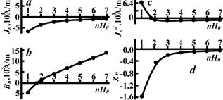
Fig. 6. Characteristics of longitudinal AS magnetic properties under external longitudinal magnetic field nH0 (H0 = 2000 A/m).
4. Conclusions
So, the longitudinal thermodiffusion AS formed in the non-equilibrium electron-hole plasma in p-InSb under the external longitudinal magnetic field is shown to gain diamagnetic properties. The point of departure for this statement is the diffusion of electrons for considerable distance from the axis of AS current filament stemmed from a high mobility in regard to holes in the thermodiffusion AS. In the longitudinal magnetic field, the electrons spin around the central hole-enriched region forming the closed orbits and create the magnetic moment Me. All orbits are mutually parallel and in total define the general magnetic moment of the whole AS M = ∑ Me.
The phenomenological treatment of the problem allows obtaining the expressions as follows:
The AS magnetization in the external magnetic field:
Jn![]() (– 0.2α
(– 0.2α![]()
![]() ;
;
The AS magnetic induction in the external magnetic field:
Bn = (1 – 0.2α![]() )Hn = µASnHn;
)Hn = µASnHn;
The AS diamagnetic magnetization in the external magnetic field:
Jnd![]() – 0.1α · Bn
– 0.1α · Bn ![]()
![]() ;
;
The AS diamagnetic susceptibility in the external magnetic field:
χn= ![]() = – 0.1α
= – 0.1α ![]()
![]() ,
,
where α = µ0e2Le2nе ![]() mе =
mе = ![]() .
.
The computation of the diamagnetic susceptibility χnand its estimation provide the large value of χ= ![]() 1.56 at H0, primarily, stemmed from large dimensions of electron spinning orbits (r ~ 10-3 сm), in the AS in the longitudinal magnetic field. Though, when increasing the external magnetic field Hn, the orbit radii vigorously decrease what leads to the same decreasing (~1/n2) in the diamagnetic susceptibility.
1.56 at H0, primarily, stemmed from large dimensions of electron spinning orbits (r ~ 10-3 сm), in the AS in the longitudinal magnetic field. Though, when increasing the external magnetic field Hn, the orbit radii vigorously decrease what leads to the same decreasing (~1/n2) in the diamagnetic susceptibility.
References
- S.V. Vonsovskii. Magnetizm. Izdatel'stvo «Nauka», Moscow, 1971, p.1032.
- A.A. Stepurenko, Fiz. Tekh. Poluprov. 28, 402 (1994).
- A.A. Stepurenko, Fiz. Tekh. Poluprov. 30, 76 (1996).
- B.S. Kerner and V. V. Osipov, Sov. Phys. JETP 36, 359 (1982).
- V.A. Vashchenko, B.S. Kerner, V.V OsipovandV.F. Sinkevich.Fiz. Tekh. Poluprov., 23, 1378 (1989).
- T. Hayashi, T. Morita, M. FukayaandE. Hasegawa. Japan J. Appl. Phys., 13. № 10. 1667 (1974).
- B.S. Kerner, V.V Osipov, M.T. Romanko, V.F. Sinkevich.Sov. Phys. JETP, 44, v. 2, 77 (1986).
- M.N. Vinoslavskii.Fiz. tverd. Tela., 31, 315 (1989).
- R. Symanczyk, E. PieperandD. Jäger. Phys. Lett. A, 143, 337 (1990).
- R. Symanczyk, S. GaelingsandD. Jäger. Phys. Lett. A, 160, 397 (1991).
- I.K. Kamilov, A.A. StepurenkoandA.S.Kovalev.Fiz. Tekh. Poluprov., 36, 187 (2002).
- C. Hilsum and A. C. Rose-Jnnes, Semiconducting III – V Compounds., Pergamon Press. Oxford / London / New York / Paris. 1961, (p.323).
- A.K. ZvezdinandV.V. Osipov.JETP, 58, 160 (1970).
- I.K. Kamilov, A.A. Stepurenko, A.E. GummetovandA.S. Kovalev.Fiz. Tekh. Poluprov., 42, 393 (2008).
- I.K. Kamilov, A.A. Stepurenko, A.E. GummetovandA.S. Kovalev.Fiz. Tekh. Poluprov., 41, 286 (2007).
- I.K. Kamilov, A.A. StepurenkoandA.E. Gummetov. Fiz. Tekh. Poluprov., 45, 456 (2011).
- I.K. Kamilov, A.A. StepurenkoandA.E. Gummetov.Fiz. Tekh. Poluprov., 44, 721 (2010).
- YU.K. Shalabutov. Vvedeniye v fiziku poluprovodnikov. Izdatel'stvo «Nauka», Leningrad, 1969, p.292.


