American Journal of Renewable and Sustainable Energy, Vol. 1, No. 3, September 2015 Publish Date: Aug. 24, 2015 Pages: 156-165
Stirling Engine Technology: A Technical Approach to Balance the Use of Renewable and Non-Renewable Energy Sources
Kwasi-Effah C. C.1, *, Obanor A. I.1, Aisien F. A.2
1Department of Mechanical Engineering, University of Benin, Benin City, Nigeria
2Department of Chemical Engineering, University of Benin,, Benin City, Nigeria
Abstract
The flexible fuel Stirling engine technology lost its place in the market more than 100 years ago due to the more compact invention of the Otto and Diesel engines. Though the Otto and Diesel engine are non-flexible fuel engines, but their smaller nature or increased work ratio made them gain wider fittings in countless industrial applications. However, due to the current global warming, climate change and energy crises involved in non-renewable energy sources; interest in Stirling engines for mitigating these global energy crises is growing once again. Worldwide increase in renewable energy usage will greatly cater for the current energy demand and increase the future sustainability of energy usage. Since most country’s economy in the world is majorly powered by non-renewable fossil, it is a big challenge to overrun our economy with renewable energy. However, fostering a flexible technology to run on either source is a viable approach to balance the use of these sources depending on the systemic availability of a particular source of energy. This paper presents an overview of the technical developments and technology trend of the Stirling engine.
Keywords
Stirling Engine, Technology Trend, Renewable Energy, Energy, Economic Crises, Global Warming
Received: July 2, 2015
Accepted: August 2, 2015
Published online: August 24, 2015
@ 2015 The Authors. Published by American Institute of Science. This Open Access article is under the CC BY-NC license. http://creativecommons.org/licenses/by-nc/4.0/
Contents
1. Introduction 2. History and Classification of Stirling Engine 3. Development Trend of the Stirling Engine 4. Thermodynamics of an Ideal Stirling Engine 4.1. Work Done by an Ideal Stirling Engine Cycle 4.2. Heat Flow in an Ideal Stirling Engine Cycle 4.3. Efficiency of an Ideal Stirling-Cycle Engine 4.4. Comparing the Ideal Stirling Engine Cycle with Ideal Otto and Ericsson Cycle 5. Discussions 6. Conclusion Nomenclature
1. Introduction
The rate of a country’s growth and development is driven by the amount of energy available in that country. Global energy demand is increasing due to rapid industrialization which began in the 21st century and increase in population (Dilip and Marika, 2009). As domestic and industrial systems make use of the available energy produced by energy systems, technological advancement is crucial for these systems to maximally utilize the available energy sources in the world thus, meet up with the expected demand. Energy source is generally classified as renewable and non renewable. Non-renewable source also called a finite source is a source of energy that does not renew itself at a sufficient rate for sustainable economic extraction in meaningful human time frames. Thus, non-renewable energy sources cannot be replaced once they are used up, they will not be restored after millions of years (USEA, 2014). An example is carbon-based, organically derived fuel. The original organic material, with the aid of heat and pressure, becomes a fuel such as oil or gas. Fossil fuels such as coal, petroleum, natural gas e.t.c are all non-renewable resources (UNDP, 2008). Renewable energy is generally defined as energy that comes from resources which are naturally replenished on a human timescale. Renewable energy resources include hydropower, wood biomass, alternative biomass fuels (e.g ethanol, biogas and bio-diesel), organic wastes, geothermal, wind, and solar. These renewable energy sources have great potential to meet the world’s energy need of the future. It has been identified that, the proportion of renewable energy and non-renewable energy usage in the world has wide overlap (IEA, 2008).The world depends majorly on non-renewable energy sources to drive its economy. This dependence on non-renewable energy source is not enough to meet up with the growing energy demand and future energy security of the country.
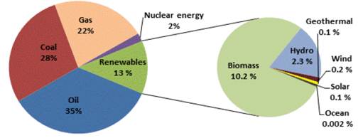
Figure 1. The distribution of energy sources and the shares of renewable energy.
Source: International energy agency IEA (2008).
Figure 1 shows that the world economy is greatly influenced and powered by non-renewable fossil fuels having about 87% of usage. The implication of this is that about 87% of renewable energy is needed in addition to 13% present renewable sources to replace non-renewable fossil fuel. Researchers have argued that it is not possible for renewable energy to replace this large percentage of energy occupied by non-renewable sources in the present human time scale due to the huge economic and technological challenge faced by renewable energy systems. Another base argument is that fossil fuel will soon finish!, perhaps not completely true since more oil reserves are being discovered within time scale. However, based on Nigeria’s present fossil fuel reserve of 37.2billion barrel crude at an average production rate of 1 billion barrel annually and 187 Trillions of standard cubic feet (Tscf) of natural gas at an average production rate of 2.4 Trillions of standard cubic feet annually (Bala and Pam, 2012), it can be estimated that non-renewable fossil fuel resource will continue to be available for hundreds of years. Also, renewable biofuel is a welcomed technological development for replenishing and producing natural gas from renewable sources. Technologies for mitigating climate change and reducing global warming caused by combustion of fossil fuel are being developed. A common method employed in such technology involves carbon dioxide capture and sequestration (Johnson, 2011). This technology encourages the use of both renewable and non-renewable fossil fuel. Capturing the green house gas produced while burning fuel such as petrol, coal, biogas or natural gas will reduce the amount of green house gas pollution, global warming and climate change and also facilitate the formation of crude under the earth when sequestrated. Hence it is imperative to find a common ground in balancing both renewable energy sources and non-renewable energy source so as to meet up with the growing demand of the world’s energy.
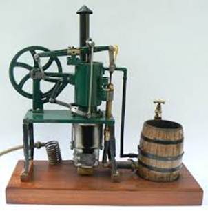
Figure 2a. A typical Stirling engine model.
Source: www.energy maxout.com/semodels
An engine which will run on multiple source of fuel has the potential to economically and technically balance the use of renewable and non-renewable source of energy. The Stirling engine is capable of utilizing different sources of heat from both renewable and non-renewable sources to generate power (Tester, et al, 2005). Thus, the flexible operation of the Stirling engine may be a renewed approach in combining renewable and non-renewable source of energy to meet up with the world’s energy. This paper discusses the technology trend of the Stirling engine and the possibility of its utilization in recent and future economy. Figure 2a and b shows a sample model of a typical Stirling engine.
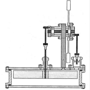
Figure 2b. Sectional view of a typical low temperature differential Stirling.
Source: www.steamengine.com.au/stirling/models
2. History and Classification of Stirling Engine
Heat engines operating on the Stirling cycle are the most efficient practical heat engines ever built (Minassians and Sanders, 2008). The Stirling engine cycle is a closed cycle engine which operates on the thermal expansion and contraction of gas to produce work. Since heat is supplied externally to the engine, a wide variety of fuel or heat sources can be used for its operation. Due to this advantage, the Stirling engine can be regarded as a multi-fuel engine.
The Stirling engine was first developed and patented by Rev. Robert Stirling in Edinburgh, Scotland in 1816 (Kolin, 1991). Robert Stirling and his brother James, one of the leading engineers of the time, worked on regenerative systems for many years. In those days similar machines were called air engines or hot-air engines or caloric engines with the name of the inventor prefixed. The name ‘Stirling Engines’ was coined to embrace all types of closed cycle regenerative gas engines regardless of the identity of the working fluid. Prior to the Stirling engine design by the Stirling brothers, several other designs appeared offering innovations such as the open cycle engine (Ericsson engine) which replenished the hot air in each cycle with fresh cold air, doing away with cooling difficulties in stirling engine but caused great heat loss and an efficiency improvement of about 2% (Vries, et al, 2014). Throughout the 19th century hot air engines were made and used in relatively large numbers. The early air engines were used in a variety of applications, mainly generation of power and pumping water. Stirling engines enjoyed substantial commercial success around 1900. However, the lack of suitable materials hampered its further development. Also, the improvements in internal combustion engines and electrical machines led to its eventual demise (Minassians and Sanders, 2008).
The Stirling engine can be classified based on its design configuration. These includes: (i) alpha type (ii) beta type and (iii) gamma type.
(i) Alpha Type
The alpha configuration has two power pistons connected in series by a heater, cooler and regenerator. It makes use of a single cylinder having an expansion space and compression space. It is mechanically simple and is capable of producing high power to volume ratio; however there are often problems related to the sealing of the expansion piston under high temperatures. The alpha engine has the smallest dead and complicated linkages to join the pistons to the crankshaft. Figure 3 shows a model configuration of the engine.
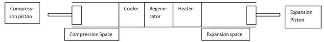
Figure 3. Alpha engine configuration.
(ii) Beta Type
In the beta type, a displacer and power piston is contained in one cylinder. This makes it quite compact and there is typically a small amount of dead space as there are no interconnecting passageways. It is mechanically simple as both piston and displacer are connected at a common point on the crankshaft, with the only difficulty arising from the fact that the connecting shaft for the displacer must pass through the piston where it must make a pressure-tight seal. Figure 4 shows a model configuration of the engine.
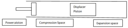
Figure 4. Beta engine configuration.
(iii) Gamma Type
The gamma type is similar to the beta since it also uses a piston and a displacer both directly connected to a common crankshaft. The difference is that they are not in the same cylinder, meaning that the problems of sealing the displacer rod through the piston are avoided. The downside for this is the introduction of a gas flow passageway which increases dead space in the engine. This configuration is probably the easiest to build, especially out of budget materials. Figure 5 shows a model configuration of the engine.
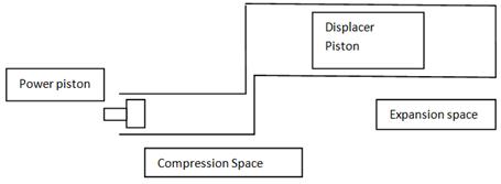
Figure 5. Gamma engine configuration.
The invention of the free piston Stirling engine is generally credited to W. T. Beale who first built it in the 1960’s as a solution to overcoming problems with lubricating the crankshaft of a traditional engine (Senft, 1982)
3. Development Trend of the Stirling Engine
Although the Stirling engine is a simple engine that does not depend on careful timing of fuel injection and ignition like an internal combustion engine, it has had a cyclic history, ranging from periods of rapid technological development to virtually total neglect. Stirling technology has been a subject of curiosity from its earliest days. The potential for demonstrating high cycle efficiencies, along with the challenge of producing a durable mechanical method for harnessing its energy, have resulted in literally thousands of Stirling engine designs finding their way into the technical and patent literature (Robert, 2007). Though the Stirling engine was invented in 1816 however, the design theory to model such type of engine was first achieved about 55 years later by a German engineer "Prof. Gustav Schmidt" (Kolin, 1991). The Schmidt analysis made so many thermodynamic assumptions in order to achieve optimization of the Stirling engine. Urieli and Berchowitz also developed thermodynamic procedures for modeling a Stirling engine which they called adiabatic analysis (Martini, 1983). While the Stirling cycle predates both the Otto and Diesel cycles, the internal combustion engine has become the preferred choice for power generation in countless applications. Several factors that must have contributed to this selection are as follows:
(a). Size and Weight – Internal combustion engines are typically smaller and lighter than Stirling engines of same power outputs. This has been particularly beneficial in automotive applications.
(b). Lubrication – Stirling engines generally require lubricants that can withstand higher temperatures than those used in internal combustion engines. It is also important to protect the working fluid of a Stirling engine from contamination by the lubricant. In some cases, this is achieved through hermetical seals, which add to the Stirling engine cost.
(c). Heat Transfer – Where as an internal combustion engine burns fuel directly in the cylinder to do work on the power piston, a Stirling engine relies on the transfer of heat through the cylinder to the working fluid. The heat flux achieved through the flames in an internal combustion engine is much higher than that achieved through the cylinder surface.
(d). Control – The fuel and air flow to an internal combustion engine are adjusted for immediate response to a change in load; whereas, it is more difficult to achieve dynamic operation with prompt response in a Stirling engine. Like size and weight, fast response is an important factor in automotive applications.
The various Stirling engine designs built from 1816 to date are presented as follows;
1. Stirling engine developed in 1 8 1 5 featured two separated cylinders: This was the first Stirling engine built by Robert Stirling. It was invented one year before the first patent. Based on the classification in section (Sesusa, 2004), it is a gamma-type engine. It is air cooled.
2. Stirling engine developed in 1816 featured two pistons in one cylinder: This engine used two pistons in only one cylinder. This was done as a result to improve the efficiency of the gamma type with an advantage of avoiding the dead volume and flow friction loss aroused by connecting rod present in gamma type. However, a major problem came up with this concept. The connecting rod of the displacer has to be led through the working piston and sealed. This configuration can be classified into a beta type engine.
3. Stirling engine developed in 1827 featured the first engine with regenerator: Two improvement of efficiency was realized in adding a regenerator in the gamma and beta type. Thin plates were placed in the displacer piston to store heat and heat up the working gas when it enters the heater. This design involved addition of more displacers with one working piston to make the motion of the engine more regular.
4. Stirling engine developed in 1840 featured a separated regenerator: To enlarge the heat transferring surface Stirling introduced a heat exchanger built up of pipes. Instead of the word regenerator it was named "plate box". The box was filled with sheets of metal (1/40 inches thick) positioned at specific spacing (1/50 inches).
5. Stirling engine developed in 1845 featured a pressurized displacement cylinder: A Stirling engine with an external pump was used to pressurize the working fluid inside the engine to increase the amount of gas. Thus, improve the work done by the engine. This engine had an average power output of about 2.5 hp. A prototype was used for 10 months to drive all the machines of the Dundee casting company in Britain. As the need for performance grew, it was displaced by a larger one of the same type. It ran for more than two years without interruption.
6. Napier-Rankine engine developed in 1854 a Heat exchanging pipes on the hot and cold side: Less than ten years after the last Stirling engine Napier and Rankine designed an engine with about 20 pipes on the hot and cold side to enlarge the heat transferring area. The engine had several rods to adjust the gap of the working piston and the displacer. It is not known if this kind of engine ever ran because of the immense dead volume.
7. Ericsson engine developed in 1860 featured an Open Stirling cycle. To avoid problems with the cooling fluid Ericsson designed the open cycle. At each rotation of the engine the hot, expanded gas was displaced by fresh air from the surroundings. Although the losses were huge and the engine only had a total efficiency of 2 % it found numerous applications for large pumps and presses.
8. Laubereau engine developed in 1861 featured an enlarged heat exchanging surface. Laubereau enlarged these surfaces on the hot and cold side by designing an engine with a small cylindrical gap around one central piston. The disadvantage is that there are immense flow losses and so the engine has a total efficiency of approximately 1.8 % (Robert, 2007).
9. Young and Kirk engine developed in 1865 featured a toothed heat transferring areas. This engine was driven by condensing steam to improve the heat exchange. The designers used huge toothed areas to improve the Stirling engine. These heat exchangers are better than pipes because no additional dead volume is raised. There are no reports about a further development of this concept.
10. Lehmann engine developed in 1866 has the characteristics of a beta type Stirling engine. In contrast to other engines this machine is water cooled. The Lehmann engine represents the beta type. Experiment on this engine was the basis for Prof. Gustav Schmidt’s theory (1871) concerning Stirling engines.
11. Laubereau engine developed in 1869 featured a discontinuous piston movement. Laubereau used the Hornblower triangle for the motion of the displacer. The technical problems diminished the practical advantages and therefore this design was not developed further. Laubereau’s engines were used for mixers and pumps in chemical laboratories of that time.
12. Ericsson engine developed in 1870 featured a solar dish-Stirling unit: This first sun driven engine was built in New York. This engine producing 1 hp needed with a concentrating surface of about 10 square feet. This concept was developed to produce energy where coal was not available.
13. Rider engine developed in 1875 had the characteristics of an alpha type engine. The Rider air engine, built by M.H.T. in London worked for up to 15 years without any interruption. Hundreds of these engines were sold all over the world. The engine performed so well that little thought was given to improvement.
14. Stenberg engine developed in 1877 had a combination Lehmann’s and Laubereau’s engine. His design was actually based on the experimental reports of Prof. Tresca from Paris, it became clear that Laubereau was very optimistic about the design of the complex connections around his central piston. Stenberg took the hot part of Laubereau and combined it with the cold part of Lehmann. In addition he improved the burner and the boiler in a way that this engine was quite successful.
15. Van Rennes engine developed in 1879 had a simplified working mechanism of the gamma type. Two connecting rods are used to drive two working pistons and displacers in two cylinders. Comparing this system with a conventional crank drive it is an enormous advantage to design and maintain only these connecting rods.
16. Robinson engine developed in 1880 featured a preheater. This invention tripled the performance of air engines without making it more complex. It made the Stirling engine more efficient than the best steam engine but it was too late as the Otto engine was already introduced and the diesel engine was just being invented. After the introduction of the Otto and diesel engine, interest in Stirling engine by engine manufacturers began to fade. Thus, displacing the Stirling engine from the market.
17. Heindrici engine developed in 1884 had the Characteristics of a gamma type: The original Stirling concept was primarily improved by the water cooler. The performance was raised because of the larger temperature difference between the hot and cold side.
18. Robinson -1889 Engine with cooling platform: Instead of a water cooler Robinson used a huge cooling platform. It was built with a kind of cooling fins later used for the cylinders of the Otto engine. The thick platform was also modified by holes to enlarge the heat exchanging surface and to improve the heat transfer by radiation and convection.
19. Ringbom engine developed in 1905. This engine is one of the first hybrid machines. The displacer is free oscillating and the working piston is mounted on a conventional crank shaft
20. Malone engine developed in 1931. Experiments showed that thin layers of water have extreme high thermal conductivities. Malone built 3 experimental engines with a heater temperature of 400 °C and a pressure of 10’000 psi.
21. Philips engine developed in 1938 was a Stirling engine designed for radio use just before the Second World War. Also, it was to be sold in regions where it is difficult to obtain batteries and where there were good supplies of wood or coal. Philips made enormous steps in the development of Stirling engines and began in the 1960’s to build refrigeration systems using the Stirling concept.
22. Meiier engine developed in 1958 featured a rhombic drive. The cooler, regenerator and preheater surround the cylindrical working space. The rhombic drive allows a complete dynamic balanced motion of all driven parts. The preheater system shown became part of almost all modern Stirling engines.
23. West engine developed in 1970 featured a liquid piston. The oscillating motion of water in the U-pipe was a non-flow process. The working gas flows from the hot to the cold side. When a part of water is displaced from the U-pipe, the total volume changes and this has the same effect as the motion of the working piston in gamma type engines.
24. Beale engine developed in 1974 was a free piston Stirling engine: In this system, the working piston and displacer are not connected by any mechanical part. The motion of the free swinging displacer is aroused by flow forces of the working fluid.
25. Nystrom engine developed in 1977 featured a special tubular heat exchanger. Almost 20 years after Meijer’s invention of the parallel device of combustion chamber and heat exchanger Nystrom designed a tubular combustion chamber with a tubular heat exchanger in a radial position.
26. United Stirling engine developed in 1978 featured an enlarged pipe preheater. The Swedish company United Stirling was founded 1968 in Malmo as part of the Swedish department of defence. One of the later inventions was a double acting Stirling engine with four cylinders. The parallel cylinders needed a complex working mechanism but because of the compact assembly the use of a heater in combination with a preheater was possible.
27. Meiier engine developed in 1982 was a wobble plate engine: The British scientist Sir William Siemens invented in 1863 a Stirling engine with wobble plate drive that was never built. This concept was modified 80 years later by Van Weenan for the early Philips program. In 1978 Meijer built a wobble plate engine with adjustable angles. This system was used for a double acting Siemens Stirling engines to control the movement of the displacer and to drive the crank shaft.
28. McDonnell Douglas engine developed in 1985 made use of solar energy. Mc Donnell Douglas used the engine of United Stirling and mounted it on a parabolic mirror with a diameter of 11 m. Using an exocentric, kardanical drive it follows the sun very precisely in the horizontal and azimuthal direction. It had an efficiency of about 31 %
29. Kolin engine developed in 1985 had the characteristics of a gamma engine. This concept is based on five main components which include: working piston, heat exchanger on the cold and hot side, displacer and regenerator. Kolin’s engine also combines a working membrane with the heat exchanger on the cold side. This results in only 3 main parts of the engine
30. Isshiki engine developed in 1988 features a Stirling engine with internal heating. The Isshiki-engine receives concentrated solar radiation, which heats up the wire mesh in the engine through a glass cover. It can be said that Stirlings design of an external heated engine is changed to an internal one. This system resembles Otto or Diesel engines.
31. Senft engine developed in 1990. This engine has the characteristics of a gamma type of engine with very low temperature difference. This engine keeps running down to a temperature difference of only 0.5 °C. The low temperature engine can be achieved by reducing the friction and flow losses to a minimum. For this concept the compression ratio is usually about 1.004:1 (Kongtragool and Wongwises, 2003).
4. Thermodynamics of an Ideal Stirling Engine
The idealized Stirling engine cycle consists of four thermodynamic processes acting on the working fluid as shown in Figure 6. It should be noted that for the ideal Stirling engine Cycle the heat-exchangers, regenerator, and transfer passages are assumed to have zero volume.
(i) Isothermal expansion process: The expansion space is heated externally, and the gas undergoes near-isothermal expansion.
(ii) Constant-volume Process: This process is also known as isovolumetric or isochoric heat removal. The gas is passed through the regenerator, thus cooling the gas, and transferring heat to the regenerator for use in the next cycle.
(iii) Isothermal compression: The compression space is intercooled, so the gas undergoes near-isothermal compression.
(iv) Constant-volume heat addition. The compressed air flows back through the regenerator and picks up heat on the way to the heated expansion space.
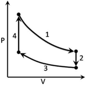
Figure 6. Pressure volume diagram of an ideal Stirling engine.
4.1. Work Done by an Ideal Stirling Engine Cycle
The net work output of a Stirling engine cycle can be evaluated by considering the cyclical integral of pressure with respect to volume:
![]() = − pdV (1)
= − pdV (1)
This can be identified as the area enclosed by the process curves on the pressure volume diagram in Figure 4. The network done is during the expansion and compression process as shown in Equation (2).
W=-[![]() +
+![]() ] (2)
] (2)
The equation of state is given by Equation (3)
pV = mRT (3)
Since T is constant for an isothermal process, and m is constant for a closed cycle, the work done during an isothermal process is given in Equation (4).
W= - ![]() (4)
(4)
The subscripts H and L denote the high and low temperature isotherms respectively.
Since V4 = V1 and V3 = V2, Equation (4) becomes:
W= -![]() ) (5)
) (5)
The work done is negative since work is done by the system to the surrounding. Equation (5) shows that the work output for the Stirling engine cycle can be increased by maximizing the temperature difference between hot and cold ends, the compression ratio, the mass of gas and either the total volume of the engine or the mean operating pressure and the specific gas constant.
4.2. Heat Flow in an Ideal Stirling Engine Cycle
The heat flowing in and out of a Stirling-cycle engine can be evaluated based on the second law of thermodynamics. This is done by considering the integral of temperature with respect to entropy:
dQ =TdS (6)
The integral of temperature with respect to entropy is given by Equation (7)
Q=∫TdS (7)
This can be visualised as the area beneath the process curves on the temperature-entropy diagram in Figure 7.
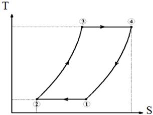
Figure 7. Temperature entropy diagram.
Since the isochoric heat transfers within the regenerator are completely internal to the cycle, i.e. -Q2®3 =Q4®1, then to evaluate the heat flows in and out of the system we need to consider only the isothermal processes. For the isothermal expansion process in a closed cycle (where T and m are constant, and where the subscripts H and L denote the high and low temperature isotherms respectively):
QH = ![]() (8)
(8)
This integral can be evaluated easily by considering the First Law of Thermodynamics
dQ = dU-dW (9)
and since:
dQ =TdS and dW=-pdV (10)
Thus,
TdS = dU + pdV
Hence heat flow during the isothermal expansion process can be expressed in terms of a change in internal energy and volume in Equation (11):
QH = ![]() +
+ ![]() (11)
(11)
Substituting Equation (3) into (11), the pressure terms can be expressed in terms of volume and temperature and noting that there is no change in internal energy (dU=0) during an isothermal process we have:
QH = ![]() (12)
(12)
For the low temperature side, since V4 = V1 and V3 = V2, we have:
QL = ![]() (13)
(13)
4.3. Efficiency of an Ideal Stirling-Cycle Engine
The efficiency of any heat engine is defined as the ratio of work output to heat input, i.e.
h= ![]() (14)
(14)
Hence an equation for the efficiency of an ideal Stirling-cycle engine can be developed by considering Equations (5) and (12):
h= ![]() (15)
(15)
This reduces to:
h= ![]() (16)
(16)
Equation (16) demonstrates that the efficiency of an ideal Stirling-cycle engine is dependant only on temperature and no other parameter. Recalling that the Carnot efficiency for a heat engine is:
hCarnot= ![]() (17)
(17)
Thus,
hStirling engine = hCarnot (18)
As stated earlier, the Stirling engine cycle has the maximum efficiency possible under the Second Law of Thermodynamics. However, it should be noted that unlike the Carnot Cycle, the Stirling-cycle engine is a practical machine that can actually be used to produce useful quantities of work.
4.4. Comparing the Ideal Stirling Engine Cycle with Ideal Otto and Ericsson Cycle
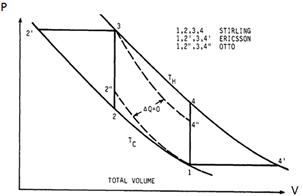
Figure 8. PV diagram of ideal Stirling engine, Ericsson and Otto engine cycle.
As mentioned earlier, the thermodynamic definition of a Stirling cycle is isothermal compression and expansion and constant volume heating and cooling as shown in process I, 2, 3, 4, I in Figure 8. The thermodynamic definition of an Ericsson cycle is isothermal compression and expansion and constant pressure heating and cooling is shown in process, I, 2', 3, 4', 1. This Ericsson cycle encompasses more area than the Stirling cycle and therefore produces more work. However, the volumetric displacement is larger, therefore, the engine is larger. There is a modern pumping engine concept which approximates this cycle. Similarly, the thermodynamic definition of the Otto cycle is adiabatic compression and expansion and constant volume heating and cooling which is shown in process 1, 2", 3, 4", 1 in Figure 8. The Otto cycle encompasses smaller area making it have less work compared to the ideal Stirling engine process. However, the volumetric displacement of the Stirling engine is almost equal to the Otto cycle thus, making it an insignificant factor of concern in the ideal case. The variable volume spaces in a Stirling engine are usually of such size and shape that their compression and expansion is essentially adiabatic since little heat can be transferred to the walls during the process of compression or expansion. An internal combustion engine approximates the Otto cycle. In real Stirling machines, a large portion of the gas is in the dead volume which is compressed and expanded nearly isothermally so the loss of work per cycle is small. Thus, this makes it have higher efficiency than the Otto Cycle.
5. Discussions
The Stirling engine cycle considered here is an ideal form. Practical Stirling engine cycles differ from the ideal cycle in several in several ways such as a nonzero volume in regenerator or heat exchanger unit. This means that the working gas is never completely in either the hot or cold end of the machine, and therefore never at a uniform temperature. The piston motion is usually semi-sinusoidal rather than discontinuous, leading to non-optimal manipulation of the working gas. The expansion and compression processes in practical Stirling engines are polytropic rather than isothermal. This causes pressure and temperature fluctuations in the working gas and leads to adiabatic and transient heat transfer losses. Fluid friction losses occur during gas displacement, particularly due to flow through the regenerator. Other factors such as heat conduction between the hot and cold ends of the machine, seal leakage and friction in kinematic mechanisms all cause real Stirling engines to differ from ideal behavior. Although Stirling engines theoretically have Carnot efficiency, the above factors tend to reduce the performance of real machines to significantly less than this value. Material strength/temperature considerations and practicalities such as the overall size of the machine usually limit the amount that the temperature, volume, or pressure can be increased. However, it is interesting to note that the specific work output can be dramatically enhanced in a Stirling engine simply by selecting a working gas with a high specific gas constant. In practice the best Stirling engines have efficiencies of more than 40 % (Kongtragool and Wongwises, 2003). The Stirling engine has the ability to run as renewable energy system. Thus, its applications in solar power generation system will be a huge success especially in this era of climate change and energy crises. Its ability to switch fuels without altering the engine also means that operators of Stirling engines are less vulnerable to rises in fuel prices or fuel shortages. The Stirling engine has the ability to run on reversible operation. If the shaft of a Stirling engine is powered with a motor then the Stirling engine can be used as a heat pump, shifting heat from the cold side to the hot side. It is possible to achieve extremely low temperatures by doing this, and there are a number of successful Stirling cryo-coolers (Robert, 2007). Since combustion occurs externally, cleaner emissions are usually achieved. Stirling engine has quiet operation due to combustion taking place externally. Low vibration is also observed in a typical balanced design. They have less moving parts than an internal combustion engine and if well designed they can last for many hours between services or overhauls. Hence low maintenance is usually achieved.
Stirling engines only operate effectively in a relatively narrow band of speeds and because increasing speed or power involves putting more heat into the engine there is thermal lag. Thus throttle response can be delayed. This factor discourages the use of Stirling engine in auto industries; however they can be used as hybrid car engines to counter this challenge. In terms of size and weight, a typical Stirling engine for a given power output in comparison with the internal combustion engine is quite large. This necessitates robust housing. It is imperative to note that application of Stirling engine in renewable energy may override the internal combustion engine in terms of life cycle cost.
6. Conclusion
This paper has been able to review the history, technical issues and development trend of the Stirling engine. Considering the merits and improving on the little technical challenge associated with the Stirling engine, this technology can be a renewed approach in mitigating global environmental and energy crises. This technology is capable of balancing the use of renewable and non-renewable source of energy, to meet up with the present global energy demand and energy sustainment of the future economy. Hence government and energy systems researchers should begin to divert knowledge into this technology so as to achieve global success in meaningful human time.
Nomenclature
| p | Pressure (Pa) |
| Q | Heat (J) |
| R | Specific gas constant (J/kgK) |
| S | Entropy (J/K) |
| T | Temperature (K) |
| U | Internal energy (J) |
| V | Volume (m3) |
| W | Work (J) |
| h | efficiency (%) |
References
- Bala E.J and Pam J.Y., (2012). Energy sources and sustainable development of the north. A Paper Presented at Conference on "The North and Strategies for Sustainable Development," organized by Arewa House, Kaduna, 5th-6thDecember.
- Dilip, A. and Marika, T., (2009). Sustainable energy for developing countries. Sapiens Journal. Vol.2 pp 293-296
- Johnsson, F., (2011). Perspectives on CO2 capture and storage. Greenhouse Gas Sci. Technol., Vol. 1, pp 119–133.
- Kolin, I., (1991). Stirling Motor: History-Theory-Practice. Zagreb University Publications, Zagreb
- Kongtragool B, Wongwises S. A., (2003). Review of solar powered Stirling engines and low temperature differential Stirling engines. Renewable and Sustainable Energy Reviews, Vol. 7 pp131–54
- Martini, W.R., (1983). Stirling engine design manual, 2nd ed. 1 NASA CR-168088, pp. 79–80
- Minassians, A. D. and Sanders, S. R., (2008). Multi- Phase Stirling engines," 6th International Energy Conversion Engineering Conference and Exhibit (IECEC)
- Robert S., (2007). History of Stirling engine. Available at http://www.stirlinqenqines.orq.uk/. Accessed 19th June, 2015
- Senft J.R., (1982). A simple derivation of the generalized Beale number. Proceedings of the 17th Intersociety Energy Conversion Engineering Conference. Los Angeles: Institute of Electrical and Electronic Engineers
- Sesusa (2004). Stirling history. Available at http://www.sesusa.org/historv. 1816.htm . Accessed 19th June, 2015
- Stirling Models. Steam and Engine of Australia. Available at http://www.steamengine.com.au/stirling/models/livesteam/pics/image1.jpg. Accessed 28th July, 2015
- Stirling engines Models. Available at http://www.energy maxout.com/semodels. Accessed 28th July, 2015
- Tester, J.W, Drake, E.M, Driscoll, M.J, Golay, M.W, Peters, W.A., (2005).Sustainable energy: choosing among options. Cambridge, MA: MIT Press. ISBN 978-0-262-20153-7
- USEA: U.S. Energy Information Administration. (2011): Emissions of green house gases report. Retrieved from U.S. Energy Information Administration: Available at http://205.254.135.24/oiaf/1605/grpt/carbon.html. Accessed 19th November, 2014
- Vries, B.J, Vuuren, D.P, Hoogwik, M.M., (2014). Renewable energy sources: global potential for the 21st century at a global level: "An integrated approach"Energy Policy Vol. 35 pp 2590–2610


