
American Journal of Renewable and Sustainable Energy, Vol. 1, No. 3, September 2015 Publish Date: Aug. 5, 2015 Pages: 115-127
Optimal Power Control for Distributed DFIG Based WECS Using Genetic Algorithm Technique
Hanan M. Askaria1, M. A. Eldessouki2, *, M. A. Mostaf2
1Egyptian Electricity Transmission Company, Abbasia Area, Cairo, Egypt
2Faculty of Engineering, Department of Elec. Power, University of Ain Shams, Cairo, Egypt
Abstract
This paper presents an improved control strategy for both the rotor side converter (RSC) and grid side converter (GSC) of a distributed doubly fed induction generator (DFIG)-based wind energy conversion system (WECS) using Genetic Algorithm (GA) technique. The primary objective of this control scheme is to track the optimal power extracted from the wind according to the power- speed curve characteristic of the wind turbine. Based on genetic algorithm technique, specific fitness functions related to both rotor and stator currents and voltages are presented in order to obtain the best values for controller gains of both RSC and GSC controllers in order to achieve an optimal output power and maintaining system dynamic stability. MATLAB /Simulink were used to build the dynamic model and simulate the system. The model performance was also compared with the detailed model developed by matlab simulink to show the validity of presented study.
Keywords
Index Terms - DFIG, GA Technique, Objective Function, PI Controller
Received: June 29, 2015
Accepted: July 10, 2015
Published online: August 4, 2015
@ 2015 The Authors. Published by American Institute of Science. This Open Access article is under the CC BY-NC license. http://creativecommons.org/licenses/by-nc/4.0/
1. Introduction
With the growing penetration of wind energy into power grids, the impact of WT on power system stability is of increasing concern. In development of the wind turbine (WT) techniques, several types of WT have been used. Recently, the WT with doubly fed induction generator (DFIG) is becoming popular [1], because its topology has many advantages in terms of variable speed operation, relatively high efficiency, four-quadrant active and reactive power capabilities, flexible control and small converter size [2]. The DFIG can supply power at constant voltage and constant frequency while the rotor speed varies. This makes the DFIG suitable for variable speed wind power generation. The main advantage of using DFIG is the fields oriented decouple control (FOC) for control of active and reactive power [1].A decouple control strategy for active and reactive power of DFIG has been explained and widely used in [3-9].
Due to their simple structure and robust performance, proportional-integral (PI) controllers are the most common controllers used in the decoupled control for the DFIG. However, the success of the PI controller, and consequently the performance of the DFIG depend on the appropriate choice of the PI gains. Find tuning the PI parameters using the traditional trial and error method to optimize the performance consumes a lot of time, and it is cumbersome especially when the system is nonlinear [10]. Recently, intelligent optimization algorithms such as genetic algorithms (GAs), tabu search algorithm, simulated annealing (SA) and particle swarm optimization (PSO) have been successfully used as optimization tools in various applications, including the online tuning of the controller parameters [11-13].
Genetic algorithm (GA)-based optimization methods is introduced in [14] to obtain the controller gains for rotor side DFIG converter with the main objective of improving the DFIG ride through capability. It has been used in static VAR compensator controller parameter design in [15], and hydro-generator governor parameter tuning in [16]. In [17], an optimum design procedure using GA’s is introduced for the controller used in the frequency converter of (VSWT) driven (PMSG).
PSO has also been employed; to design the optimal control for the WT with DFIG in [18], in optimal design of automatic voltage controller [19]. It used to adjust the DFIG controllers gains with the objective of reducing the rotor current [18.] and also to improve the small-signal stability [20].
In this paper GA technique has been employed to optimize the controller parameters of both RSC and GSC of DFIG based WT in order to validate good power tracking performance and thus confirming the effectiveness of this proposed control strategy. A detailed model for representation DFIG based wind farm in power system dynamics simulations is presented. MATLAB/SIMULINK dynamic software program is used for this study [matlab 2008].
2. DFIG Based WECS
A. Wind Energy Conversion System Background
The aerodynamic model of the wind turbine can be characterized by the Cp −λ –β curves. Cp is the power coefficient, which is a function of tip speed ratio λ and pitch angle β. The tip speed ratio λ is given by [21].
![]() (1)
(1)
The relationship of Cp, λ and β can be described as [22]:
![]() (2)
(2)
![]() (3)
(3)
The coefficients c1 to c6 are: c1 = 0.5176, c2 = 116, c3 = 0.4, c4 = 5, c5 = 21 and c6 = 0.0068. Maximum value of Cp (Cpmax = 0.48) is achieved for β = 0 degree, at the optimal tip speed ratio. This particular value of λ is about λopt = 8.1. The Cp- λ characteristics is illustrated in Fig. 1. The output power of the turbine is given by the following equation:
![]() (4)
(4)
The target optimum power from a wind turbine can be written as [23]:
![]() (5)
(5)
![]() (6)
(6)
Fig. 2 illustrates the optimal mechanical power at different wind speeds. From the figure, the turbine mechanical power is a function of rotor speed at various wind speeds. The power for a certain wind speed has its maximum value at a certain rotor speed called optimum rotor speed which is corresponds to the optimum tip speed ratio λopt.
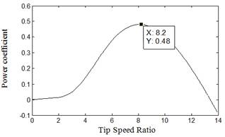
Fig. 1. Power Coefficient as a function of Tip Speed Ratio.
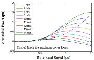
Fig. 2. Mechanical power as a function of turbine rotational speed at different wind speed.
B. DFIG Model
The simplified schematic diagram of the wind energy conversion system based on a DFIG, studied in this paper is shown in Fig 3. In this diagram, mechanical energy is produced by a WT and provided to a DFIG through a gear box. The stator winding of the DFIG is directly connected to the grid, whereas the rotor winding is fed by back to back pulse width modulation (PWM) converter. The grid side converter (GSC) is connected to the grid via three chokes to improve the current harmonic distortion. The rotor side converter (RSC) controls the power flow from the DFIG to the grid by controlling the rotor currents of the DFIG [24]. The mathematical model of DFIG, in per unit notation in d–q reference frame is given bellow [10,25]:
![]() (7)
(7)
![]() (8)
(8)
![]() (9)
(9)
![]() (10)
(10)
![]() (11)
(11)
![]() (12)
(12)
![]() (13)
(13)
![]() (14)
(14)
where
![]()
The dynamic equation of DFIG is given as:
![]() (15)
(15)
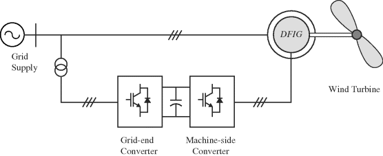
Fig. 3. Schematic diagram of the wind energy conversion system.
3. Genitic Algorithm Based Optimal control
A genetic algorithm (GA) is a method for solving both constrained and unconstrained optimization problems based on a natural selection process that mimics biological evolution. The algorithm repeatedly modifies a population of individual solutions. At each step, the genetic algorithm randomly selects individuals from the current population and uses them as parents to produce the children for the next generation. Over successive generations, the population "evolves" toward an optimal solution [22].
The genetic algorithm works as the following steps:
A. Initial Population
The algorithm begins by creating a random initial population. The initial population usually contains 20 individuals, which is the default value of Population size in population options in matlab.
B. Creating next Generation
At each step, the genetic algorithm uses the current population to create the children that make up the next generation. The algorithm selects a group of individuals in the current population, called parents, who contribute their genes—the entries of their vectors—to their children. The algorithm usually selects individuals that have better fitness values as parents. The genetic algorithm creates three types of children for the next generation:
Elite children are the individuals in the current generation with the best fitness values. These individuals automatically survive to the next generation.
Crossover children are created by combining the vectors of a pair of parents in the current population. At each coordinate of the child vector, the default crossover function randomly selects an entry, or gene, at the same coordinate from one of the two parents and assigns it to the child.
Mutation children are created by introducing random changes, or mutations, to a single parent. Fig. 4 presents the flowchart steps of GA technique.
To use the GA solver, we need to provide at least two input arguments, a fitness function and the number of variables that are the controller gains in this study. Besides the boundaries of the parameters that necessary to limit the solution with in ranges that called the design space.
4. Simulation Results
The proposed GA strategy has been tested for validation using DFIG whose ratings are given in Matlab detailed model of DFIG [22]. The wind speed in this model is maintained constant at 10 m/s. A remote fault occurs on the 120 kv system during the period of (0.1 – 0.13 s) as shown in Fig. 5. We will compare the improvement obtained in the system dynamic performance when applying GA procedure to design the controller gains, with those results obtained using the classical PI controller that used in Matlab. For the same operation condition, GA is used to obtain the optimal controller gains for the rotor and stator side converters.
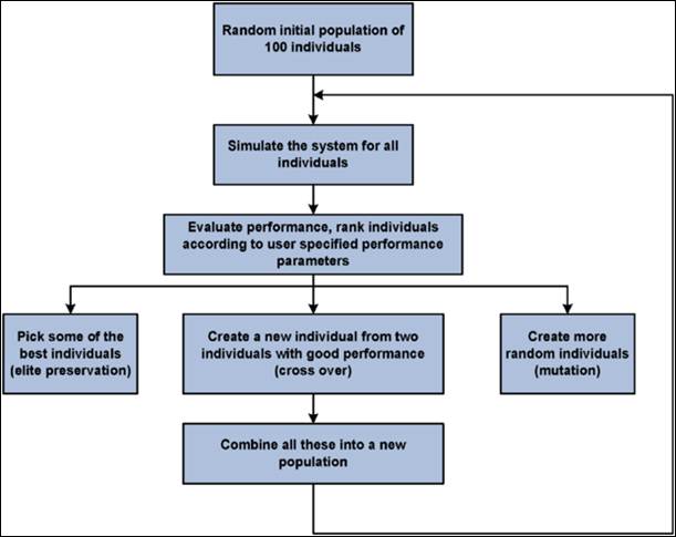
Fig. 4. GA Technique.
The control strategy aims to get measured values of the power absorbed to the grid equal or closer to the reference values. The reference active power is generated based on the wind speed value and wind turbine characteristics as mentioned in (5), while the reactive power is determined as a function of the desired reactive power converter compensation. In this study, the reference reactive power is set to zero. The control system uses a torque controller in order to maintain the turbine speed at 1.09 pu.
In the GSC and RSC control loops, there are four PI controllers and each of them has proportional gain and integral gain. The behaviour of the converter depends on the control system. By tuning these controllers, the grid side and rotor side converter’s performance will be improved to achieve the optimal grid power without affecting the dynamic system performance. In order to achieve this goal, the following objective function for RSC will be designed [14]:
![]()
![]() (16)
(16)
To control the GSC controller gains, another objective function will be added:
![]()
![]() (17)
(17)
Whereiqg, idg, iqr, idr, vdg, vqg, vdr and vqr are the quadreture and direct components of both RSC and GSC currents and voltages.
The main goals to design the proposed objective functions are to minimize the over currents in both RSC and GSC circuits through the terms in the functions related to the grid and rotor side converter currents (iqg, idg, iqr and idr) besides reducing the controller voltages as possible through the terms related to (vdg, vqg, vdr and vqr), therefore, minimize losses as well as optimal power utilization. So GA technique will be applied to find automatically the optimal parameters for both RSC and GSC controllers in order to optimize the objective fitness functions. The controller parameters of the system can be divided into two sets, four proportional – integral gains for GSC controller namely, (KP1, KI1, KP2 and KI2) that express the controller gains of DC Voltage link (outer loop) and grid currents (inner loops). Another four controller gains for RSC (KP3, KI3, KP4 and KI4) express the gains of stator reactive power (outer loop) and rotor currents (inner loops) respectively. This will be carried out through the following two cases:
Case 1: Applying GA for both RSC and GSC using objective functions F1 and F2.
Case 2: Applying GA for RSC only in order to optimize the first objective function that related to the rotor side converter.
The boundaries for controller gains and their optimal values that resulted from using GA solver for both cases are shown in Tables I, II. The results are shown in Figures 6 to 23. The model performance was also compared with the detailed model developed by matlab simulink to show the validity of presented study.
On general, the figures, by comparing the results with those given using the classical PI controllers, illustrate that when using GA technique, the dynamic response will be improved for each of rotor and grid reference and measured currents that expressed by the first and second terms in the objective functions which minimize the error between the reference and measured currents. This reflects in a better dynamic performance for other DFIG quantities, especially for the grid power curve which obviously becomes closer to its reference value and thus the main objective from the proposed GA technique will be achieved. The oscillations of rotor voltage are reduced significantly, thus contributing to better DFIG safety, and it’s very imperative to the grid voltage stability.
The dc link voltage oscillations obviously decrease and become nearest to its reference value even in case 2 where the objective function is applied only for RSC, because of the third term in the objective function that attained to optimize the rotor voltage response. On general, the dc-link voltage oscillations in both cases do not affect the continuous operation of the system and consequently improving the DFIG dynamic performance. Noteworthy that the tuning of GSC controller gains using GA as in case 1, compared with case 2, contributes in reducing the transient occurred through the fault time interval in each of active and reactive power curves as seen in the figures.
Overall, the GA based on the fitness objective functions used, prove a quality to get the best tuning for the controller gains in order to track the reference value of the power extracting from the wind based on wind speed according to (5), besides maintaining the dynamic system stability.
Note that, the average value of power in both cases 1 and 2 are around 0.48 while the average value for the reference is about 0.47; it means a good power tracking has been occurred in both cases. From the results of Figures and Tables, it is cleared that the RSC controller is the most effective factor to control the power. Noted that KI4 using GA technique; has different two values if we compare between case 1 and 2, while KP4 has the same value in both cases.This drives us to understand the effect of the control gains. While the proportional controller reduces the rise time, increase the overshoot, decrease the settling time but with small amount and reduce the steady state error, the integral controller has a double effect. So we have left an important conclusion; since the GA technique for GSC was not optimized (case 2), reducing the over current in rotor circuit will cost increasing the integral gain of rotor inner loop (KI4), thus decreasing the settling time, steady state error and oscillations in the power curve profile.
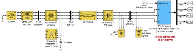
Fig. 5. Detailed simulink model of DFIG.
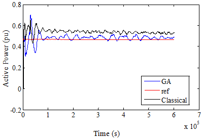
Fig. 6. Active power in case 1 over 3s.
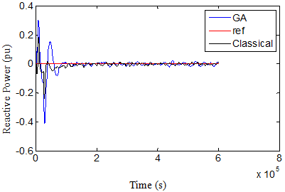
Fig. 7. Reactive power in case 1 over 3s.
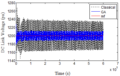
Fig. 8. DC Link voltage in case 1 over 3s.
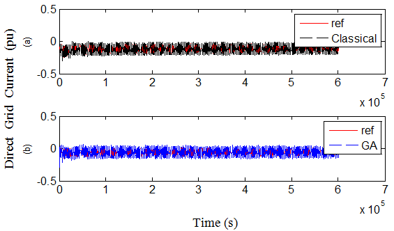
Fig. 9. Direct grid current in case 1 over 3s, (a)classical, (b) GA.
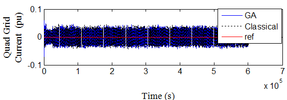
Fig. 10. Quad grid current in case 1 over 3s.
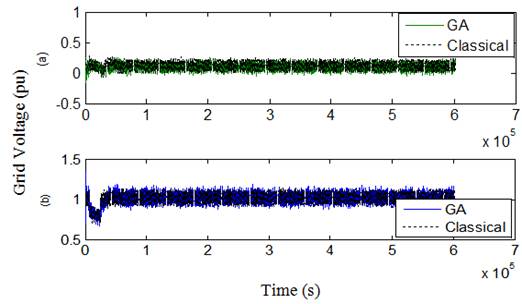
Fig. 11. Grid voltage in case 1 over 3s (a) Quad component, (b) Direct component.
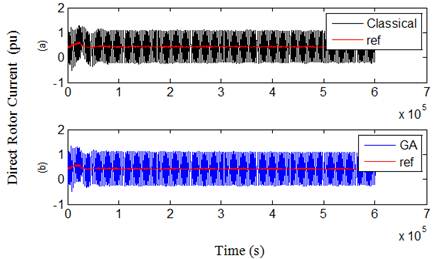
Fig. 12. Direct rotot current in case 1 over 3s (a) Classical (b) GA
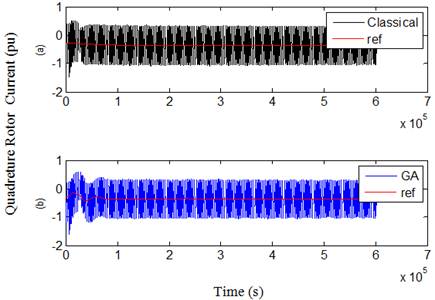
Fig. 13. Quad rotot current in case 1 over 3s. (a) Classical (b) GA
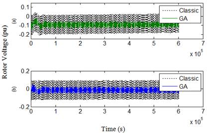
Fig. 14. Rotor voltage in case 1 over 3s. (a) Quad component, (b) Direct component.
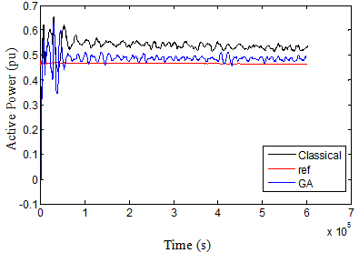
Fig. 15. Active power in case 2 over 3s
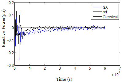
Fig. 16. Reactive power in case 2 over 3s.
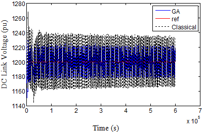
Fig. 17. DC voltage in case 2 over 3s.
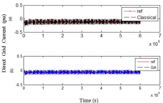
Fig. 18. Direct grid current in case 2 over 3s (a)classical, (b) GA.
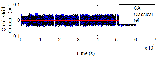
Fig. 19. Quad grid current in case 2 over 3s.
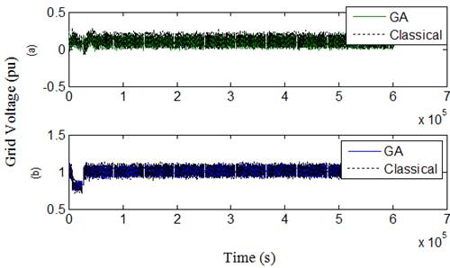
Fig. 20. Grid voltage in case 2 over 3s. (a) Quad component, (b) Direct component.
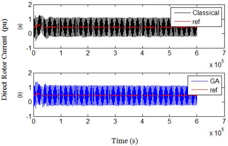
Fig. 21. Direct rotot current in case 2 over 3s. (a) Classical (b) GA.
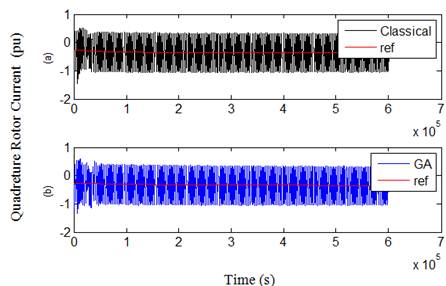
Fig. 22. Quad rotot current in case 2 over 3s. (a) Classical (b) GA.
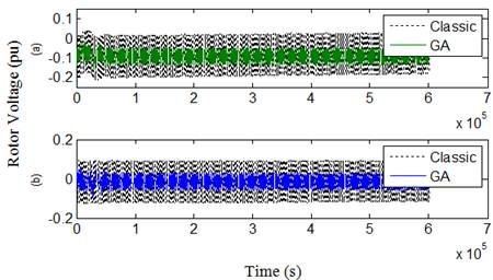
Fig. 23. Rotor voltage in case 2 over 3s. (a) Quad component, (b) Direct component.
Table 1. Controller gains In case 1.
| Gains | Values | ||
| LB | UB | GA Result | |
| KP1 | 0 | 0.01 | 0.0061 |
| KI1 | 0.01 | 0.1 | 0.01733 |
| KP2 | 1 | 10 | 2.5709 |
| KI2 | 400 | 600 | 400.0042 |
| KP3 | 0 | 0.1 | 0.001 |
| KI3 | 1 | 20 | 15.082 |
| KP4 | 0.05 | 1 | 0.050353 |
| KI4 | 1 | 20 | 1.0175 |
Table 2. Controller gains In case 2.
| Gains | Values | ||
| LB | UB | GA Result | |
| KP3 | 0 | 0.1 | 0.013 |
| KI3 | 1 | 20 | 1.34 |
| KP4 | 0.05 | 1 | 0.054 |
| KI4 | 1 | 20 | 10.589 |
5. Conclusion
The simulation results show that the proposed GA technique based on the fitness objective function, prove a quality to find the best values of controller gains in the control loops of DFIG rotor and grid side converters in order to track the optimal power that can be extracted from the wind according to the power - speed curve of wind turbine characteristic. A complete simulation model is developed using MATLAB Simulink environment. An important conclusion is emerged; since the GA controller for GSC was not optimized, reducing the over current in rotor circuit will cost increasing the integral gain of rotor current and this will lead to decrease the settling time, steady state error and oscillations in the power curve profile.
Nomenclature
|
| Tip speed ratio and Power coefficient. |
|
| Wind speed. |
|
| Pitch angle (degree) |
|
| Blade length. |
|
| Rotational speed of turbine. |
|
| Stator voltage (pu) |
|
| Rotor voltages (pu) |
|
| Stator currents (pu) |
|
| Rotor currents (pu) |
|
| Base speed (rad/s) |
|
| Electrical stator and rotor speed (pu). |
|
| Stator magnetic fluxes linkage (pu). |
|
| Rotor magnetic fluxes linkage (pu). |
|
| Stator and rotor resistances (pu). |
|
| Stator and rotor inductances (pu) |
|
| Magnetizing inductance (pu) |
| H | System inertia constant (s) |
|
| Torque developed by the turbine (pu) |
|
| Electromagnetic torque (pu) |
References
- Eriksen, P.B., Ackermann, T., Abildgaard, H., Smith, P., Winter, W., and Rodriguez Garcia, J.M.,‘System operation with high wind penetration’, IEEE Power Energy Mag., 2005, 3, (6), pp. 65–74.
- Dongkyoung Chwa and Kyo-Beum Lee, "Variable Structure Control of the Active and Reactive Powers for a DFIG in Wind Turbines", IEEE Transactions on industry applications, Vol. 46, NO. 6, Nov/Dec 2010, 2545.
- Yamamoto, M., and Motoyoshi, O.,‘Active and reactive power control for doubly-fed wound rotor induction generator’, IEEE Trans. Power Electron., 1991, 6, (4), pp. 624–629.
- R. Datta and V. T. Ranganathan, "A simple position sensorless algorithm for rotor side field oriented control of wound rotor induction machine," IEEE Trans. Ind. Electron. Soc., vol. 48, pp. 786–793, Aug. 2001.
- Rajib Datta and V. T. Ranganathan, "Direct Power Control of Grid-Connected Wound Rotor Induction Machine Without Rotor Position Sensors ", IEEE Transactions on power electonics, Vol. 16, No. 3, May 2001.
- Hassan Abniki1, Mahmood Abolhasani, and Mohammad Ehsan Kargahi, "Vector Control Analysis of Doubly-Fed Induction Generator in Wind Farms", Energy and Power 2013, 3(2): 18-25 DOI: 10.5923/j.ep.20130302.02.
- Gilsung Byeon, and Gilsoo Jang , "Modeling and control of a doubly-fed induction generator (DFIG) wind power generation system for real-time simulations", Journal of Electrical Engineering and Technology vol. 5, No. 1, pp. 61~69, 2010, 61.
- Amit Kumar Jain, and V. T. Ranganathan, "Wound Rotor Induction Generator With Sensorless Control and Integrated Active Filter for Feeding Nonlinear Loads in a Stand-Alone Grid", IEEE Transaction on industrial electronics, vol. 55, No. 1, January 2008.
- Radia Abdelli, Toufik Rekioua, AbdelmounaïmTounzi, "Iomproved direct torque control of an induction generator used in a wind conversion system connected to the grid radia", ISA Transactions52 (2013) 525–538.
- Hany M. Hasanien, Essam A. Al-Ammar, "Dynamic response improvment of doubly fed induction generator–based wind farm using Fuzzy logic controller", Journal of Electrical Engineering, vol. 63, NO. 5, 2012, 281–288.
- Abido M. A., "Robust design of multimachine power system stabilizers using simulated annealing",IEEE Trans Energy Conver 2000; 15(3): 297-304.
- Ruiz-Cruz R, Sanchez EN, Ornelas-Tellez F, Loukianov AG, "Particle Swarm Optimization for Discrete-Time Inverse Optimal Control of a Doubly Fed Induction Generator" , IEEE Trans Cybernet 2012; 99: 1-12.
- Adel A.A. Elgammal, "Optimal Design of PID Controller for Doubly-Fed Induction Generator-Based Wave Energy Conversion System Using Multi- Objective Particle Swarm Optimization",Journal of Technology Innovations in Renewable Energy, 2014, 3, 21-30.
- João P. A. Vieira, Marcus V. A. Nunes and Ubiratan H. Bezerra (2011). "Using Genetic Algorithm to Obtain Optimal Controllers for the DFIG Converters to Enhance Power System Operational Security", Wind Turbines,Dr. Ibrahim Al-Bahadly (Ed.), ISBN: 978-953-307-221-0, InTech, Available from: http://www.intechopen.com/books/wind-turbines/using-genetic-algorithm-to-obtain-optimal-controllers-for-thedfig-converters-to-enhance-power-system.
- Ju, P., Handschin, E., and Reyer, F., ‘Genetic algorithm aided controller design with application to SVC’, IEE Proc., Gener. Transm. Distrib., 1996, 143, (3), pp. 258–262.
- Lansberry, J.E., and Wozniak, L., ‘Adaptive hydrogenator governor tuning with a genetic algorithm’, IEEE Trans. Power Syst., 1994, 9, (1), pp. 179–183.
- Hany M. Hasanien, and S. M. Muyeen., "Design Optimization of Controller Parameters Used in Variable Speed Wind Energy Conversion System by Genetic Algorithms", IEEE Transactions on Sustainable Energy, vol. 3, NO. 2, April 2012.
- Qiao, W., Venayagamoorthy, G.K., and Harley, R.G., "Design of optimal PI controllers for doubly fed induction generators driven by wind turbines using particle swarm optimization". 2006 Int. Joint Conf. on Neural Networks, July 2006, Vancouver, BC, Canada, pp. 1982–1987.
- Abido, M.A., "Optimal design of power-system stabilizer using particle swarm optimization", IEEE Trans. Energy Convers., 2002, 17, (3), pp. 406–413.
- Wu F., Zhang X. P., Godfrey K., and Ju P., "Small Signal Stability Analysis and Optimal Control of a Wind Turbine with Doubly Fed Induction Generator", IET Generation, Transmission and Distribution. Vol. 1, No. 5. pp. 751-760, 2007.
- Lei Tian, Qiang Lu, Wen-zhuo Wang, "A Gaussian RBF Network Based Wind Speed Estimation Algorithm for Maximum Power Point Tracking", Lei Tian et al./ Energy Procedia 12 (2011) 828 – 836.
- Mathwork Matlab R2008.
- Jogendra Singh Thomas and Mohand Ouhrouche (2011). MPPT Control Methods in Wind Energy Conversion Systems, Fundamental and Advanced Topics in Wind Power,Dr. Rupp Carriveau (Ed.), ISBN: 978-953-307-508-2, InTech, Available from:http://www.intechopen.com/books/fundamental-and-advancedtopics-in-wind-power/mppt-control-methods-in-wind-energy-conversion-systems.
- E. Bounadjaa, A. Djahbarb, Z. Boudjemac, "Variable structure control of a doubly fed induction generator for wind energy conversion systems",Energy Procedia 50 ( 2014 ) 999 – 1007.
- Soens, J. Driesen, J. Belmans, R., " A Comprehensive Model of a Doubly Fed Induction Generator for Dynamic Simulations and Power System Studies", in Proc. International Conference on Renewable Energies and Power Quality, Vigo, Spain, April 2003.
Biography
|
|
|
|
|
|