
American Journal of Renewable and Sustainable Energy, Vol. 1, No. 3, September 2015 Publish Date: Jul. 20, 2015 Pages: 90-101
A New Cycle for Combined Hydrogen and Power Generation
Ehsan Khanehabad1, Abtin Ataei1, *, Hossein Reza Darabi2, Jun-Ki Choi3
1Department of Energy Engineering, Graduate School of the Environment and Energy, Science and Research Branch, Islamic Azad University, Tehran, Iran
2Chemistry & Chemical Engineering Research Center of Iran, Tehran, Iran
3Department of Mechanical and Aerospace Engineering, University of Dayton, Dayton, Ohio, USA
Abstract
Hydrogen is being considered as an environmentally friendly fuel that has a potential to reduce the dependency on fossil fuels significantly. This paper presented a new cycle for combined hydrogen and power production in which, power is generated in a gas turbine cycle and the waste heat from the exhaust of the gas turbine is recovered to produce hydrogen in a five step thermochemical copper-chlorine cycle. The thermodynamic analysis of the combined cycle was performed by coding in Engineering Equation Solver (EES) software and was adapted to a combined hydrogen and power generation plant with capacity of 1 t/h hydrogen production. The results showed that the combined cycle may generate 174 MW of power, the energy efficiency may reach to 45% and the required helium mass flow rate is 48.58 kg/s.
Keywords
Gas Turbine, Copper-Chlorine Cycle, Power, Hydrogen, Combined Cycle
Received: June 10, 2015
Accepted: June 25, 2015
Published online: July 15, 2015
@ 2015 The Authors. Published by American Institute of Science. This Open Access article is under the CC BY-NC license. http://creativecommons.org/licenses/by-nc/4.0/
1. Introduction
The world faces a huge use of the depleting fossil energy resources which cause releasing greenhouse gases into the atmosphere. The greenhouse gases have destructive effects on the environment and cause extensive climate change [1-3]. Nowadays, fossil energy is neither abundantly available nor cheap, and also due to the carbon dioxide generation while consuming, it should be controlled by appropriate policy to avoid unnecessary consumptions. Many scientists and researchers all over the world are working on alternative energy carriers which can be abundantly available and cause less environmental pollutions. Hydrogen can be considered as a competitive alternative energy because it is abundantly available in the nature, has a high heating value and its utilizing releases no greenhouse gases. Therefore, scientists and researchers have taken a new concept into consideration, known as Hydrogen economy era [4].
Hydrogen is mostly used as a chemical material in petrochemical processes [5] and is produced by methods like coal gasification or steam-methane reforming [5-7] which are totally dependent on fossil energy resources and greenhouse gases during the production are generated. Therefore, novel methods for hydrogen production should be developed. Among new methods presented for hydrogen production, electrolysis and thermochemical cycles which respectively use electricity and heat to produce hydrogen, are becoming more economical, environment friendly and popular [8-11].
The heat required in the thermochemical hydrogen production methods can be supplied by waste heat recovery or generated by fossil fuel or other types of fuels. Scientists and researchers attempt to supply that heat demand from renewable energy sources or nuclear energy. Pregger et al. [10] suggested solar energy to supply the heat required in the thermochemical hydrogen production methods. Flether [12] thermodynamically analyzed the thermochemical hydrogen production cycles using solar energy. Orhan et al. [3] calculated the Exergetic efficiency associated with those thermochemical processes. Some of the researchers considered geothermal heat as a good resource and because of that they developed the suitable thermochemical cycles which can work with geothermal heat [11,13,14]. Due to the shortage and limitations of renewable energy sources, many scientists and researchers have considered nuclear thermal heat for thermochemical cycles [15, 17] and because of the extensive advantages of this thermal resource, the future of world’s hydrogen production is known to be nuclear hydrogen.
One of the most promising thermochemical cycles is Cu-Cl cycle which is considered as a low temperature cycle. Orhan described the different steps of this cycle which is coupled with nuclear thermal energy [18-22]. Nateter et al. obtained the heat required for different stages of Cu-Cl cycle [23]. Lewis et al. investigated the performance of this cycle from the production cost point of view [24,25].
This paper presents a new cycle for combined power and hydrogen production in which, the heat required for the thermochemical cycle of Cu-Cl is provided indirectly by fossil fuels and is obtained from the exhaust of a gas turbine plant. It should be noted that gas turbine plants usually cost less than steam plants and also release less pollutants to the environment [26] and it is common that the exhaust heat is used in a steam plant cycle to generate more electricity. On the other hand, one of the problems of the thermal plants is the inability of storing the power in case of not having enough loads in the 24 hours of a day which may cause inefficiency. Because the new cycle presented in this paper generates combined power and hydrogen, it makes a possibility to store the excess power in form of hydrogen. Therefore, the hydrogen production is increased during the off-peak time of the gas turbine.
It means that instead of generating electricity with a high efficiency which does not have enough clients during the off peak time, the combined cycle produces more hydrogen with a capability of storage or sale.
Firstly, we introduce the new cycle for combined hydrogen and electricity generation which we called it Khanehabad cycle. Then, the thermodynamic analysis of the cycle, which was performed by coding in Engineering Equation Solver (EES) software, is presented. And finally, the cycle's power generation and energy efficiency will be calculated.
2. Material and Methods
2.1. Gas Turbine Cycle
Brayton cycle is the ideal cycle for gas turbine power plants as it is shown in Figure 1. It includes four main parts; air compressor, combustion chamber, turbine and electricity generator.
The cycle's mode of operation is that the ambient air is sucked by the compressor and pressure is increased to the designed pressure. Then, the compressed air is introduced to the combustion chamber and by fuel entering the chamber, the combustion process happens under a constant pressure condition. Afterwards, the hot and pressurized gas enters the turbine and during the isentropic expansion, the hot gas exits from the turbine at a pressure near the ambient pressure and is discarded to the environment. The electricity is produced by a generator which is powered by the gas turbine [27].
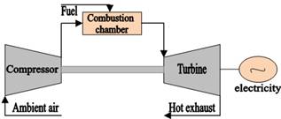
Figure 1. Gas turbine power plant.
2.2. Five Step Cu-Cl Cycle
The copper-chlorine thermochemical cycle consists of five different chemical processes in which, hydrogen can be separated from water by providing the heat and electricity required for the processes. Maximum required temperature of this cycle is reported 550 degree centigrade [28].
Table 1. The different stages of the thermochemical copper-chlorine cycle.
| T (oC) | Primary chemical reaction | Step |
| 400 | 2CuCl2(s)+H2O(g)→ CuO.CuCl2(s)+2HCl(g) | 1 |
| 500 | CuO.CuCl2(s) → 2CuCl(l)+1/2O2(g) | 2 |
| 25-80 | 4CuCl(s)+ H2O →2CuCl2(aq) +2Cu(s) | 3 |
| >100 | CuCl2(aq) → CuCl2(s) | 4 |
| 430-475 | 2Cu(s)+2HCl(g)→H2 (g)+2CuCl(l) | 5 |
Source: Modified from Rosen et al. (2006)
Different steps of this cycle are shown in Table 1. As shown in that table, reaction 5 is the main reaction of the copper-chlorine cycle in which, hydrogen is produced in temperature of 450°C from the reaction between copper and hydrochloric acid. According to that reaction, no trace of water is present in the primary materials. The water which presents in reaction 1, is in contact with CuCl2(s), hydrochloric acid and generates CuO.CuCl2(s). The reaction 3 generates copper, the other reactant required for reaction 1, and reactions 2 and 4 provide the required conditions for the thermochemical cycle. Water, heat and some electricity are the inputs of the thermochemical cycle to generate hydrogen.
2.3. The New Cycle for Combined Power and Hydrogen Production
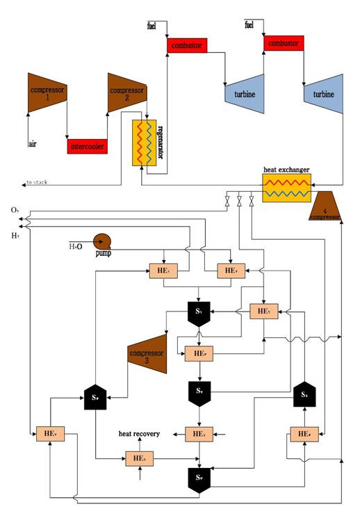
Figure 2. The flow chart of the Khanehabad cycle.
As seen, one of the basic requirements of hydrogen production in the introduced thermochemical cycle is the thermal energy at maximum temperature of 500oC. This heat is usually obtained from burning fossil fuels or thermal energy generated in a nuclear reactor. Using fossil fuels to supply that heat will introduce more greenhouse gases to the atmosphere. Although nuclear hydrogen production brings non-fossil hydrogen which is one of the promising methods of non-fossil hydrogen production in the future, it requires high knowledge and technology and therefore it cannot be extensively used all over the world. To minimize the environmental impacts, the heat required in the introduced hydrogen production cycle should be supplied by a waste heat recovery. This paper introduces an integration of gas turbine cycle and the thermochemical hydrogen production cycle to combined hydrogen and power production with a minimum greenhouse gases generation. In that novel combined cycle, which we call it Khanehabad cycle, the heat required for the Cu-Cl thermochemical hydrogen production cycle is supplied by a exhaust heat recovery from the gas turbine cycle. The flow chart of this cycle is illustrated in Figure 2. As seen, the air enters the compressor 1 at ambient temperature and pressure and then is compressed to an intermediate pressure. Then the hot compressed air enters the intermediate heat exchanger to get cooled down to the ambient temperature and enters the compressor 2 to achieve the designed pressure. The high pressured air passes through a heat exchanger, regenerator, so that its energy content is increased by the heat of the exhaust gas. At this stage, combustion occurs by fuel entering the combustion chamber and therefore, high pressure-high temperature air enters to the gas turbine and is expanded to a specific pressure. In this stage, it enters to the second combustion chamber and its temperature is increased to the hot input gases of turbine 1. The compressed high temperature air enters to turbine 2 and expands to the ambient pressure. The power is generated in the gas turbine by the generator coupled to the turbine. The hot exhaust gas of the turbine with the temperature of more than 500°C (depending on the design parameters) goes to a heat exchanger and transfers the required heat to helium as an intermediate fluid for the thermochemical copper-chlorine cycle. Accordingly, helium supplies the required heat for the different steps of the copper-chlorine thermochemical cycle.
In the copper-chlorine cycle, water enters the cycle as the primary material and is pressurized to the designed pressure using a pump, then passes through the heat exchangers 1 and 2 and obtains the heat required for the steps 2 and 5. Then, it converts to steam with temperature of 400°C and then enters the chemical reactor 1. After reacting with CuO.CuCl2, it produces CuO.CuCl2(s) and HCl(g).
The pressure and temperature of the produced HCl(g) are increased through a compressor. Then, it goes to the reactor 5 and hydrogen and CuO.CuCl2(s) are produced in a reaction with Cu(s). In stage 1, it passes through heat exchanger 3 and its temperature gets increased to 500°C. Finally, it enters the chemical reactor 2, loses oxygen and converts to CuCl(l).
Since the temperature of CuCl(l) is high, its temperature falls while passing through the heat exchanger 4, because of that temperature reduction, liquid CuCl turns to solid, and achieves the designed temperature of stage 3, which is the electrolyzer. At this stage, in contact with water, CuCl(s) produces Cu(s) and CuCl2 which are required for stages 5 and 1, respectively. As the required CuCl2(aq) for stage 1 is in solid phase, CuCl2 should pass through the heat exchanger 5 so that by increasing temperature to more than 100°C, water in CuCl2 evaporates and then the solid CuCl2 is separated from the steam by passing through a flash dryer. The steam separated at this stage returns to stage 3 once again. Solid CuCl2 enters the stage 1's reactor after passing through the heat exchanger 6 and its temperature is increased to 400°C which is the required temperature for the reaction at stage 1.
On the other hand, Cu(s) produced at the stage 3, should be heated to 450°C in order to participate in the hydrogen generation reaction. Hence, it passes through the heat exchanger 7 and then goes to the chemical reactor 5 and produces hydrogen and CuCl(l) in contact with HCl(g). The produced hydrogen gets ready to be delivered after cooling down. CuCl(l) cools down while passing through the heat exchanger 8 and turns to solid to be used in the reactor 3 as a reactant.
2.4. Thermodynamic Analysis
An EES coding was developed to do thermodynamic analysis of the presented cycle. The EES codes are given in the Appendix. Figure 3 shows the materials and energy flows in the presented cycle which were used for the thermodynamic analysis in EES. The codes developed in EES may simulate and optimize the cycle thermodynamically and estimate the energy efficiency of the cycle. The heat exchangers 1, 2, 4 and 8 and chemical reactors 3, 4 and 5 do not need any heat, or if more heat required, that thermal energy will be obtained by an internal heat recovery. Hence, no heat streams shown in that figure. In addition, the followings assumptions are considered as the defaults in this analysis:
• The production capacity of hydrogen in the Khanehabad cycle is considered 1 ton/h.
• This cycle operates under the reference conditions as atmospheric pressure and temperature of 25 °C.
• All processes operate under steady-state flow conditions.
• The pressure ratio in compressor is considered as 11.4.
• The intermediate pressure of the intercooler is 3.42 atm.
• The turbines and compressors isentropic efficiencies are 90% and regenerator isentropic efficiency is 85%.
• The combustion chamber temperature is considered as 1150°C.
• All the thermochemical reactions take place at 101 kPa.
• The Enthalpy of formation and the constants of the Shomate equation for the chemical components are given in Table2.
According to Figure 3, the work produced in the turbines (Wturbines) and consumed in the compressors (Wcompressors) can be calculated as follows;
![]() (1)
(1)
![]() (2)
(2)
Where, hi is enthaply of the stream of i. The i is the number of streams as shown in Figure 3.
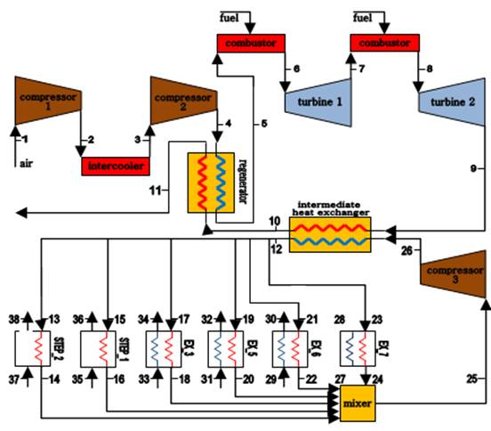
Figure 3. The energy and material flows in the Khanehabad cycle used in the EES model presented in the Appendix.
Therefore, the net work produced (Wnet) by Khanehabad cycle can be calculated as follow;
![]() (3)
(3)
The inlet heat (qin) is;
![]() (4)
(4)
The power efficiency of the cycle (ηpower) is defined s follow;
![]() (5)
(5)
Thermal efficiency of Khanehabad cycle (ηKhanehabad cycle) is calculated as follow;
![]() (6)
(6)
Where, ![]() is low heat value of the Hydrogen produced in the Khanehabad cycle.
is low heat value of the Hydrogen produced in the Khanehabad cycle.
To analyze the processes by EES software, the enthalpies are extracted from the data bank of the software. Then, the formation enthalpies are calculated using the following equation;
![]() (7)
(7)
Where, h is enthalpy, ho is enthalpy at the reference condition, T is the temperature in degrees of Kelvin and A,B,C,D,E, F and H are the constants of the Shomate equation [19,29] which are given in Table 2.
Table 2. The Enthalpy of formation and the constants of the Shomate equations for the chemical components.
| Chemical | A | B | C | D | E | F | G | H | f(kJ/kmol) |
| CuCl(S) | 75.2710 | -26.8321 | 25.6916 | -7.3580 | -1.8478 | -165.7299 | 174.6644 | -138.0720 | -138.072 |
| Cu(S) | 17.7289 | 28.0987 | -31.2529 | 13.9724 | 0.0686 | -6.0566 | 47.8959 | 0.0000 | 0 |
| CuCl2(S) | 70.2188 | 23.3613 | -14.8687 | 4.0539 | -.3662 | -228.9405 | 184.6378 | -205.8532 | -205.850 |
| CuO(S) | 48.56494 | 7.498607 | -.055980 | 0.013851 | -.760082 | -173.4272 | 94.85128 | -156.0632 | -156.060 |
| CuCl(l) | 66.9440 | -3.70E-10 | 2.17E-10 | -3.90E-11 | -9.18E-12 | -151.1374 | 174.7653 | -131.1780 | -131.180 |
Source: Given from Ref.[29].
It should be noted that the heat required for the copper-chlorine thermochemical process is given from reference [30]. Table 3 presents the heat required for the heat exchangers in the thermochemical part of the Khanehabad cycle.
Table 3. The heat required for the thermochemical part of the Khanehabad cycle.
| T(°C)∆ | H(kJ/mol H2)∆ | Component |
| 400 | 120.2 | Step 1 |
| 500 | 125.5 | Step 1 |
| 500→400 | 20.8 | HE3 |
| 150→20 | 57.6 | HE5 |
| 400→150 | 61.3 | HE6 |
| 450→20 | 32.5 | HE7 |
3. Results and Discussion
The EES model showed that the energy efficiency of the Khanehabad cycle which has 1 ton/h capacity of hydrogen production is 44.7%. According to the simulation results, the cycle's power output for production of 1000 kg/h (0.277 kg/s) of hydrogen is about 173.675 MW of electricity and the required helium mass flow rate is 48.58 kg/s. Table 4 shows the temperatures at different points of the cycle according to Figure 3.
Table 4. The temperature at different points of the cycle shown in Fig. 3.
| Point | Temperature(°C) | Point | Temperature(°C) |
| 1 | 25 | 18 | 405 |
| 2 | 180.6 | 19 | 650 |
| 3 | 25 | 20 | 25 |
| 4 | 154.2 | 21 | 650 |
| 5 | 513.4 | 22 | 405 |
| 6 | 1150 | 23 | 650 |
| 7 | 991.5 | 24 | 25 |
| 8 | 1150 | 25 | 422.3 |
| 9 | 675 | 26 | 425.7 |
| 10 | 573.9 | 27 | 20 |
| 11 | 219.6 | 28 | 450 |
| 12 | 650 | 29 | 150 |
| 13 | 650 | 30 | 400 |
| 14 | 505 | 31 | 20 |
| 15 | 650 | 32 | 150 |
| 16 | 405 | 33 | 400 |
| 17 | 650 | 34 | 500 |
The simulation results concluded the followings:
a) If the hydrogen production increases, the cycle's energy efficiency will be decreased, as shown in Figure 4. Therefore, that increase in hydrogen production should be applied during the off-peak time of the gas turbine power plant. Then, it illustrates that instead of generating electricity with a high efficiency which does not have enough clients during the off peak time, the combined cycle produces more hydrogen with a capability of storage or sale. In addition, it is a fact that in terms of economic issues, hydrogen production can have a higher economic efficiency. It means that the thermal efficiency cannot simply represent all aspects of a comprehensive analysis.
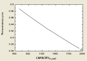
Figure 4. Hydrogen production capacity vs. the cycle's energy efficiency.
b) By increasing the hydrogen production capacity, the required helium mass flowrate increases, as shown in Figure 5.
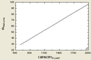
Figure 5. Hydrogen production capacity vs. the required helium mass flowrate.
c) As the hydrogen production capacity of the cycle is increased, the thermal recovery increases and the exhaust gas temperature decreases, as shown in Fig. 6.
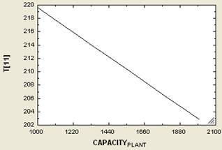
Figure 6. Hydrogen production capacity vs. the exhaust gas temperature at the atmospheric pressure.
d) As seen in Figure 7, as the hydrogen production capacity increases, the electricity generation capacity decreases.
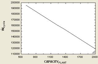
Figure 7. Hydrogen production capacity vs. gas turbine power generation.
4. Conclusion
Hydrogen is being considered as an environmentally friendly fuel that has a potential to reduce the dependency on fossil fuels significantly. Hydrogen can be produced from a number of sources, such as water, hydrocarbon fuels, biomass, hydrogen sulfide, boron hydrides, and chemical elements with hydrogen. Because hydrogen is not available anywhere as a separate element, it needs to be separated from the aforementioned sources, for which energy is necessary to do this disassociation. The forms of energy that can drive a hydrogen production process can be classified in four categories: thermal, electrical, photonic, and biochemical energy. These kinds of energy can be obtained from primary energy (fossil, nuclear, and renewable) or from recovered energy through various paths. The literature is quite large and covers many options. Many researchers have been involved in analyzing the different hydrogen production methods based on energy and exergy analysis.
In this paper, a new cycle for combined hydrogen and power production was presented. In that cycle which we call it Khanehabad cycle, power is generated in a gas turbine cycle and the waste heat from the exhaust of the gas turbine is recovered to produce hydrogen in a five step thermochemical copper-chlorine cycle. The thermodynamic analysis of the combined cycle was performed by coding in Engineering Equation Solver (EES) software. This analysis confirms the reasonable performance of the cycle to produce hydrogen using the waste heat. The EES model was adapted to a combined hydrogen and power generation plant with capacity of 1 t/h hydrogen production. The results showed that the combined cycle may generate 174 MW of power, the energy efficiency may reach to 45% and the required helium mass flow rate is 48.58 kg/s. The model also showed that if the hydrogen production increases, energy cycle efficiency, gas turbine power generation and the temperature of the gas turbine's exhaust gas will be decreased but the waste heat recovery and mass flowrate of helium required for the processes will be increased. Therefore, that increase in hydrogen production should be applied during the off-peak time of the gas turbine power plant.
The economic analysis of the Khanehabad cycle, finding the optimum point of the electricity-hydrogen production and also presenting outlines to enhance cycle's energy efficiency will be addressed in the authors' next paper.
Appendix
The EES coding developed to do thermodynamic analysis of Khanehabad Cycle is as follow;
"Thermodynamics Analysis of Khanehabad Cycle"
"CAPACITY_PLANT for H2 production cycle, kg/hr"
"state 1:"
T[1]=25
P[1]=101.325
h[1]=ENTHALPY(Air,T=T[1])
s[1]=ENTROPY(Air,T=T[1],P=P[1])
"state 2:"
s_s[2]=s[1]
P[2]=393
T_s[2]=TEMPERATURE(Air,s=s_s[2],P=P[2])
h_s[2]=ENTHALPY(Air,T=T_s[2])
eta_c1=0.9
eta_c1=(h_s[2]-h[1])/(h[2]-h[1])
T[2]=temperature(Air,h=h[2])
s[2]=entropy(Air,T=T[2],P=P[2])
"state 3:"
P[3]=P[2]-30
T[3]=25
h[3]=ENTHALPY(Air,T=T[3])
s[3]=ENTROPY(Air,T=T[3],P=P[3])
"state 4:"
s_s[4]=s[3]
P_ratio=11.4
P_ratio=P[4]/P[1]
T_s[4]=TEMPERATURE(Air,s=s_s[4],P=P[4])
h_s[4]=ENTHALPY(Air,T=T_s[4])
eta_c2=0.9
eta_c2=(h_s[4]-h[3])/(h[4]-h[3])
T[4]=TEMPERATURE(Air,h=h[4])
s[4]=ENTROPY(Air,T=T[4],P=P[4])
"state 5:"
eta_reg=((h[5]-h[4])/(h[10]-h[4]))
eta_reg=.85
T[5]=TEMPERATURE(Air,h=h[5])
p[5]=p[4]-30
"state 6:"
T[6]=1150
P[6]=P[5]
s[6]=ENTROPY(Air,T=T[6],P=P[6])
h[6]=ENTHALPY(Air,T=T[6])
"state 7:"
s_s[7]=s[6]
P[7]=650
T_s[7]=TEMPERATURE(Air,s=s_s[7],P=P[7])
h_s[7]=ENTHALPY(Air,T=T_s[7])
eta_t1=0.9
eta_t1=(h[7]-h[6])/(h_s[7]-h[6])
T[7]=TEMPERATURE(Air,h=h[7])
s[7]=ENTROPY(Air,T=T[7],P=P[7])
"state 8:"
T[8]=T[6]
P[8]=P[7]
s[8]=ENTROPY(Air,T=T[8],P=P[8])
h[8]=ENTHALPY(Air,T=T[8])
"state 9:"
s_s[9]=s[8]
P_ratio=P[6]/P[9]
T_s[9]=TEMPERATURE(Air,s=s_s[9],P=P[9])
h_s[9]=ENTHALPY(Air,T=T_s[9])
eta_t2=0.9
eta_t2=(h[9]-h[8])/(h_s[9]-h[8])
T[9]=TEMPERATURE(Air,h=h[9])
s[9]=ENTROPY(Air,T=T[9],P=P[9])
"state 10:"
m_dot*(h[9]-h[10])=m_dot_Heliume*(h[12]-h[26])
T[10]=TEMPERATURE(Air,h=h[10])
"state 11:"
h[5]-h[4]=h[10]-h[11]
T[11]=TEMPERATURE(Air,h=h[11])
"state 12:"
T[12]=650
p[12]=150
h[12]=ENTHALPY(Helium,T=T[12],P=P[12])
"state 13:"
h[13]=h[12]
T[13]=T[12]
"state 14:"
m_dot[13]=m_dot[14]
m_dot[13]*h[13]-m_dot[14]*h[14]=delta_H_step2
h[14]=ENTHALPY(Helium,T=T[14],P=P[14])
T[14]=505
P[14]=102
delta_H_step2=(CAPACITY_PLANT/3600)*496*125.5
"state 15:"
h[15]=h[12]
T[15]=T[12]
"state 16:"
m_dot[15]=m_dot[16]
m_dot[15]*h[15]-m_dot[16]*h[16]=delta_H_step1
h[16]=ENTHALPY(Helium,T=T[16],P=P[16])
T[16]=405
P[16]=102
delta_H_step1=(CAPACITY_PLANT/3600)*496*120.2
"state 17:"
h[17]=h[12]
T[17]=T[12]
"state 18:"
m_dot[17]=m_dot[18]
m_dot[33]=m_dot[34]
m_dot[17]*h[17]-m_dot[18]*h[18]=(m_dot[34]/2)*(h_cuo[34]-h_cuo[33])+(m_dot[33]/2)*(h_cucl2[34]-h_cucl2[33])
(m_dot[34]*.37)*(h_cuo[34]-h_cuo[33])+(m_dot[33]*.63)*(h_cucl2[34]-h_cucl2[33])=delta_H_HE3
h[18]=ENTHALPY(Helium,T=T[18],P=P[18])
T[18]=405
P[18]=102
delta_H_HE3=(CAPACITY_PLANT/3600)*496*20.8
h_cuo[33]=h_bar_cuo_33+A_33*T_star_33+B_33*(T_star_33^2/2)+C_33*(T_star_33^3/3)+D_33*(T_star_33^4/4)-E_33*(1/T_star_33)+F_33-H_33
A_33=48.56494
B_33=7.498607
C_33=-.055980
D_33=.013851
E_33=-.760082
F_33=-173.4272
G_33=94.85128
H_33=-156.0632
h_bar_cuo_33=1963
T[33]=400
T_star_33=(T[33]+273.15)/1000
h_cuo[34]=h_bar_cuo_34+A_34*T_star_34+B_34*(T_star_34^2/2)+C_34*(T_star_34^3/3)+D_34*(T_star_34^4/4)-E_34*(1/T_star_34)+F_34-H_34
A_34=48.56494
B_34=7.498607
C_34=-.055980
D_34=.013851
E_34=-.760082
F_34=-173.4272
G_34=94.85128
H_34=-156.0632
h_bar_cuo_34=1963
T[34]=500
T_star_34=(T[34]+273.15)/1000
h_cucl2[33]=h_bar_cucl2_33+A_33_cucl2*T_star_33+B_33_cucl2*(T_star_33^2/2)+C_33_cucl2*(T_star_33^3/3)+D_33_cucl2*(T_star_33^4/4)-E_33_cucl2*(1/T_star_33)+F_33_cucl2-H_33_cucl2
A_33_cucl2=70.21882
B_33_cucl2=23.36132
C_33_cucl2=-14.86876
D_33_cucl2=4.053899
E_33_cucl2=-.366203
F_33_cucl2=-228.9405
G_33_cucl2=184.6378
H_33_cucl2=-205.8532
h_bar_cucl2_33=1531
h_cucl2[34]=h_bar_cucl2_34+A_34_cucl2*T_star_34+B_34_cucl2*(T_star_34^2/2)+C_34_cucl2*(T_star_34^3/3)+D_34_cucl2*(T_star_33^4/4)-E_34_cucl2*(1/T_star_34)+F_34_cucl2-H_34_cucl2
A_34_cucl2=70.21882
B_34_cucl2=23.36132
C_34_cucl2=-14.86876
D_34_cucl2=4.053899
E_34_cucl2=-.366203
F_34_cucl2=-228.9405
G_34_cucl2=184.6378
H_34_cucl2=-205.8532
h_bar_cucl2_34=1531
"state 19:"
h[19]=h[12]
T[19]=T[12]
"state 20:"
m_dot[19]=m_dot[20]
m_dot[31]=m_dot[32]
m_dot[19]*h[19]-m_dot[20]*h[20]=(15*m_dot[31]/16)*(h_cucl2[32]-h_cucl2[31])+(m_dot[32]/16)*(h_H2o[32]-h_H2o[31])
(15*m_dot[31]/16)*(h_cucl2[32]-h_cucl2[31])+(m_dot[32]/16)*(h_H2o[32]-h_H2o[31])=delta_H_HE5
h[20]=ENTHALPY(Helium,T=T[20],P=P[20])
T[20]=25
P[20]=102
delta_H_HE5=(CAPACITY_PLANT/3600)*496*57.6
h_cucl2[32]=h_bar_cucl2_32+A_32_cucl2*T_star_32+B_32_cucl2*(T_star_32^2/2)+C_32_cucl2*(T_star_32^3/3)+D_32_cucl2*(T_star_32^4/4)-E_32_cucl2*(1/T_star_32)+F_32_cucl2-H_32_cucl2
A_32_cucl2=70.21882
B_32_cucl2=23.36132
C_32_cucl2=-14.86876
D_32_cucl2=4.053899
E_32_cucl2=-.366203
F_32_cucl2=-228.9405
G_32_cucl2=184.6378
H_32_cucl2=-205.8532
h_bar_cucl2_32=1531
T[32]=150
T_star_32=(T[32]+273.15)/1000
h_cucl2[31]=h_bar_cucl2_31+A_31_cucl2*T_star_31+B_31_cucl2*(T_star_31^2/2)+C_31_cucl2*(T_star_31^3/3)+D_31_cucl2*(T_star_31^4/4)-E_31_cucl2*(1/T_star_31)+F_31_cucl2-H_31_cucl2
A_31_cucl2=70.21882
B_31_cucl2=23.36132
C_31_cucl2=-14.86876
D_31_cucl2=4.053899
E_31_cucl2=-.366203
F_31_cucl2=-228.9405
G_31_cucl2=184.6378
H_31_cucl2=-205.8532
h_bar_cucl2_31=1531
T[31]=20
T_star_31=(T[31]+273.15)/1000
h_H2o[31]=ENTHALPY(Steam,T=T[31],P=P[31])
h_H2o[32]=ENTHALPY(Steam,T=T[32],P=P[32])
P[31]=102
P[32]=102
"state 21:"
h[21]=h[12]
T[21]=T[12]
"state 22:"
m_dot[21]=m_dot[22]
m_dot[30]=m_dot[29]
m_dot[21]*h[21]-m_dot[22]*h[22]=m_dot[30]*(h_cucl2[30]-h_cucl2[29])
m_dot[30]*(h_cucl2[30]-h_cucl2[29])=delta_H_HE6
h[22]=ENTHALPY(Helium,T=T[22],P=P[22])
T[22]=405
P[22]=102
delta_H_HE6=(CAPACITY_PLANT/3600)*496*61.3
h_cucl2[30]=h_bar_cucl2_30+A_30_cucl2*T_star_30+B_30_cucl2*(T_star_30^2/2)+C_30_cucl2*(T_star_30^3/3)+D_30_cucl2*(T_star_30^4/4)-E_30_cucl2*(1/T_star_30)+F_30_cucl2-H_30_cucl2
A_30_cucl2=70.21882
B_30_cucl2=23.36132
C_30_cucl2=-14.86876
D_30_cucl2=4.053899
E_30_cucl2=-.366203
F_30_cucl2=-228.9405
G_30_cucl2=184.6378
H_30_cucl2=-205.8532
h_bar_cucl2_30=1531
T[30]=400
T_star_30=(T[30]+273.15)/1000
h_cucl2[29]=h_bar_cucl2_29+A_29_cucl2*T_star_29+B_29_cucl2*(T_star_29^2/2)+C_29_cucl2*(T_star_29^3/3)+D_29_cucl2*(T_star_29^4/4)-E_29_cucl2*(1/T_star_29)+F_29_cucl2-H_29_cucl2
A_29_cucl2=70.21882
B_29_cucl2=23.36132
C_29_cucl2=-14.86876
D_29_cucl2=4.053899
E_29_cucl2=-.366203
F_29_cucl2=-228.9405
G_29_cucl2=184.6378
H_29_cucl2=-205.8532
h_bar_cucl2_29=1531
T[29]=150
T_star_29=(T[29]+273.15)/1000
"state 23:"
h[23]=h[12]
T[23]=T[12]
"state 24:"
"state 22:"
m_dot[23]=m_dot[24]
m_dot[28]=m_dot[27]
m_dot[23]*h[23]-m_dot[24]*h[24]=m_dot[28]*(h_cu[28]-h_cu[27])
m_dot[28]*(h_cu[28]-h_cu[27])=delta_H_HE7
h[24]=ENTHALPY(Helium,T=T[24],P=P[24])
T[24]=25
P[24]=102
delta_H_HE7=(CAPACITY_PLANT/3600)*496*32.5
h_cu[28]=h_bar_cu_28+A_28_cu*T_star_28+B_28_cu*(T_star_28^2/2)+C_28_cu*(T_star_28^3/3)+D_28_cu*(T_star_28^4/4)-E_28_cu*(1/T_star_28)+F_28_cu-H_28_cu
A_28_cu=17.7289
B_28_cu=28.0987
C_28_cu=-31.2529
D_28_cu=13.9724
E_28_cu=0.0686
F_28_cu=-6.0566
G_28_cu=47.8959
H_28_cu=0
h_bar_cu_28=0
T[28]=450
T_star_28=(T[28]+273.15)/1000
h_cu[27]=h_bar_cu_27+A_27_cu*T_star_27+B_27_cu*(T_star_27^2/2)+C_27_cu*(T_star_27^3/3)+D_27_cu*(T_star_27^4/4)-E_27_cu*(1/T_star_27)+F_27_cu-H_27_cu
A_27_cu=17.7289
B_27_cu=28.0987
C_27_cu=-31.2529
D_27_cu=13.9724
E_27_cu=0.0686
F_27_cu=-6.0566
G_27_cu=47.8959
H_27_cu=0
h_bar_cu_27=0
T[27]=20
T_star_27=(T[27>]+273.15)/1000
"state 25:"
m_dot[14]+m_dot[16]+m_dot[18]+m_dot[20]+m_dot[22]+m_dot[24]=m_dot_Heliume
m_dot[14]*h[14]+m_dot[16]*h[16]+m_dot[18]*h[18]+m_dot[20]*h[20]+m_dot[22]*h[22]+m_dot[24]*h[24]=m_dot_Heliume*h[25]
T[25]=TEMPERATURE(Helium,h=h[25],P=102)
"state 26:"
w_com_3=v*deltap
v=VOLUME(Helium,T=T[25],P=102)
deltap=2*30
m_dot_Heliume*(h[26]-h[25])=w_com_3
W_dot_com3=m_dot_Heliume*w_com_3
T[26]=TEMPERATURE(Helium,h=h[26],P=162)
"Thermal efficiency:"
w_turbine=abs(h[6]-h[7])+abs(h[8]-h[9])
w_compressor=abs(h[2]-h[1])+abs(h[4]-h[3])
w_net=w_turbine-w_compressor
q_in=(h[6]-h[5])+(h[8]-h[7])
eta_power=w_net/q_in
"Net power gennerated"
m_dot=500
W_dot_cycle=m_dot*w_net-W_dot_hydrogen_cycle-W_dot_com3
"w_dot_hydrogen_cycle: "
W_dot_hydrogen_cycle=(CAPACITY_PLANT/3600)*496*97.6
"Thermal efficiency of Khanehabad cycle:"
eta_khanehabad_cycle=(LHV_H2+W_dot_cycle)/(Q_net)
LHV_H2=(CAPACITY_PLANT/3600)*496*240
Q_net=m_dot*q_in
References
- Veziroglu T.N., Sahin S. 21st century's energy: hydrogen energy system. Energy Conversion and Management 2008, 49(7), 1820-31.
- Dincer I. Environmental and sustainability aspects of hydrogen and fuel cell systems. International Journal of Energy research 2007, 31, 29-55
- Orhan MF, Dincer I, Rosen MA. Exergoeconomic analysis of a thermochemical copper-chlorine cycle for hydrogen production using specific exergy cost method. Thermochimica. Acta. 2008, doi:10.1016/j.tca.2009.08.008.
- Bose T, Malbrunot P. Hydrogen: facing the energy challenges of the 21st century. Paris: John Libbey Eurotext, 2007
- Rosen MA. Advances in hydrogen production by thermochemical water decomposition: A review. International Journal of Energy 2010, 35, 1068-76
- Kothari R, Buddhi D, Sawhney RL. Comparison of environmental and economic aspects of various hydrogen production methods. Renewable and sustainable Energy Reviews 2008, 12, 553-63
- Evan BCR, Allen RWK. A figure of merit assessment of the routes to hydrogen. International Journal of Hydrogen Energy 2005, 30, 809-19
- Beghi GE. Adecade of research on thermochemical hydrogen at the joint research center, ISPRA. International Journal of Hydrogen Energy1986, 11(12):761-71
- Funk JE. Thermochemical hydrogen production: past and present. International Journal of Hydrogen Energy 2001, 26(3),185-90
- Pregger T, Graf D, Krewitt W, Sattler C, Roeb M, Moller S. prospects of solar thermal hydrogen production processes. International Journal of Hydrogen Energy 2009, 34, 4256-67
- Balta MT, Dincer I, Hepbasli A. Thermodynamic assessment of geothermal energy use in hydrogen production. International Journal of Hydrogen Energy 2009, 34(7), 2925-39
- Fletcher EA. Solar thermal processing: a review. Journal of Solar Energy Engineering 2001, 123, 63-74
- Balta MT, Dincer I, Hepbasli A. Potential methods for geothermal-based hydrogen production. In: proceedings of the international conference on hydrogen production (ICH2P-09). May 03-06, 2009, Oshawa, Canada: University of Ontario Institute of Technology. pp. 225-42
- Balta MT, Dincer I, Hepbasli A. Geothermal-based hydrogen production using thermochemical and hybrid cycles: a review and analysis. International Journal of Hydrogen Energy 2010, 34(9), 757-75
- Bertel E, Nuclear energy- the hydrogen economy. Nucl Energy Agency News 2004, 22:10-3
- Duffey R, Green atoms. Power Energy 2005, 2(2), 8-12
- Marchetti C. Long term global vision of nuclear-produced hydrogen. Int. J Nucl Hydrogen Prod Appl 2006, 1(1), 13-9
- Orhan MF, Dincer I, Rosen MA. The oxygen production step of a cooper-chlorine thermochemical water decomposition cycle for hydrogen production: energy and exergy analysis. Chemical Engineering Science 2009, 64, 860-9
- Orhan MF, Dincer I, Rosen MA. Energy and exergy analysis of the fludized bed of a copper-chlorine cycle for nuclear-based hydrogen production via thermochemical water decomposition. Chemical Engineering Research and Design 2009, 87, 684-94
- Orhan MF, Dincer I, Rosen MA. Thermodynamic analysis of the copper production step in a copper-chlorine cycle for hydrogen production. Thermochimica Acta 2008, 480, 22-9
- Orhan MF, Dincer I, Rosen MA. Energy and exergy assessments of the hydrogen production step of a copper-chlorine thermochemical water splitting cycle driven by nuclear-based heat. International Journal of Hydrogen Energy 2008, 33, 6456-66
- Orhan MF, Dincer I, Rosen MA. Energy and exergy analysis of the drying step of a copper-chlorine thermochemical cycle for hydrogen production. International Journal of Exergy 2009, 6(6), 793-808
- Naterer GF, Gabriel K, Wang ZL ,Daggupati VI, Gravelsins R. Thermochemical hydrogen production with a copper- chlorine cycle. I. Oxygen release from copper oxychloride decomposition. International Journal of Hydrogen Energy 2008, 33, 5439
- Lewis MA, Masin JG, O'Hare PA. Evaluation of alternative thermochemical cycles – part I. The methodology. International Journal of Hydrogen Energy 2009, 34990, 4115-24
- Lewis MA, Ferrandon Ms, Tatterson DF, Mathias P. Evaluation of alternative thermochemical cycle – part III further development of the Cu-Cl cycle. International Journal of Hydrogen Energy 2009, 34(9), 4136-45
- Polyzakis AL, Koroneos C, Xydis G. optimum gas turbine cycle for combined cycle power plant. Int J Energy Conversion and Management 2008, 49(4), 551-63
- Cengel YA, Boles MA. Thermodynamics: An Engineering Approach (7e).1998
- Balta MT, Dincer I, Hepbasli A. Energy and exergy analysis of new four-step copper-chlorine cycle for geothermal-based hydrogen production. International Journal of Energy 2010 , 35, 3263-72
- National Institute of Standards and Technology (NIST), http://Webbook.nist.gov/chemistry/form-ser.html.
- Orhan MF. Conceptual design, analysis and optimization of nuclear-based hydrogen production via copper-chlorine thermochemical cycle: A thesis submitted in partial fulfillment of the requirements for the degree of doctor of philosophy in The Faculty of Engineering and Applied Science, Mechanical Engineering Program, University of Ontario Institute of Technology, 2011.


