
International Journal of Energy Science and Engineering, Vol. 1, No. 4, September 2015 Publish Date: Jul. 31, 2015 Pages: 141-147
Design and Validation of Hook Used in Double Spring Balancer for the Suspension of Weight Using FEA Technique
Sampath S. S., Sawan Shetty, Chithirai Pon Selvan M.*
School of Engineering & Information Technology, Manipal University, Dubai, United Arab Emirates
Abstract
The design and manufacturing of a double spring balancer which is used to suspend the machine is carried out. Based on the design, a pattern of the element is built for the process of manufacturing. Present work deals with the optimization of the hook which is a part of the balancer which has a trapezoidal cross-sectional area. This study focuses on both bending stresses with the consideration of both tensile & compressive stresses along with displacement censorial axis with respect to neutral axis. The design which is obtained by finite element analysis technique is compared with the classical design equations and the required validation is carried out.
Keywords
Curved Beam, Spiral Spring Mechanism, Conical Drum Pulley, Ansys, Creo Pro 5.0
Received: June 30, 2015
Accepted: July 16, 2015
Published online: July 28, 2015
@ 2015 The Authors. Published by American Institute of Science. This Open Access article is under the CC BY-NC license. http://creativecommons.org/licenses/by-nc/4.0/
1. Introduction
Spring Balancers are specially designed to free the operator from the weight of hand tools. The balancers can be pulled down with least pressure, without any strain or fatigue. Spring balancing is a well known technique in mechanism synthesis to achieve equilibrium throughout the range of motion. A spring balance consists of a coiled spring fixed to a support at one end, with a hook at the other to which the body to be weighed is applied. Within the spring's limit of elasticity, the distance through which it is stretched is directly proportional to the weight of the applied body. The main advantage of a double balancer is not only providing better support to the machines when it is lifted but also it adds safety to it.
A double balancer can carry more loads compared to a single balancer and work done using the double balancer will be more effective. The use of a double balancer also increases stability of the machine and also it is safer as stoppers are applied every 2 inches apart if spring failure occurs, which makes it easy to use [4]. The hook which is a main member of the double balancer is an important member, it is designed and analyzed using finite element software [5]. The deformations and the stresses which are obtained are compared with the theoretical calculations. Crane Hooks are highly liable components that are typically used for industrial purposes. It is basically a hoisting fixture designed to engage a ring or link of a lifting chain or the pin of a shackle or cable socket and must follow the health and safety guidelines [3].
2. Related Papers
Bhasker [1] et. al tried to optimize the cross sectional area of curved beam, by properly selecting the parameters. The study focused on analysis of trapezoidal section curved beam with the help of Ansy's software. Maximum stress in the system is determined. Yogesh Tripathi & Joshi [2] constructed a solid model of crane hook which is prepared with the help of CATIA (Computer Aided Three Dimensional Interactive Application) software. Pattern of stress distribution in 3D model of crane hook is obtained using ANSYS software. The stress distribution pattern is verified for its correctness on model of crane hook using Winkler-Bach theory for curved beams. B Nagaraju [3] et. al made an attempt with the consideration of four different types of cross sections of crane hooks and is designed theoretically by using curved beam concept. CATIA software is used for modeling the crane hook and ANSYS software used to find out the stresses. As a conclusion, the results obtained from ANSYS and theoretical calculations are compared. Chetan N. Benkar [4] et al prepared a solid model and analyzed using Ansys 14 software. Finite Element Analyses have been performed on various models of crane hook having triangular, rectangular, circular and trapezoidal cross sections. Sayyedkasim Ali [5] et. al optimized the cross section of crane which is inclined towards the material saving during manufacturing of crane hook. For material saving the maximum stress region is to be identified by using FEM analysis and then material is removed by considering the maximum bending stress at failure point. Gopichand [6] worked on optimization of design parameters which is carried out using Taguchi method, total three parameters are considered with mixed levels and L16 orthogonal array is generated .The optimum combination of input parameters for minimum Vonmises stresses are determined. Dinesh and Naveen Chandran [7] studied the stress which is induced on the crane hook leading to failure. Analysis is carried out using Ansys software. Tushar Hire & Barataria [8] used analytical and experimental methods to analyze the stress pattern in crane hooks. Also they determined the failure criteria of a hook.
|
| 1 Forged Hooks |
| 2 Safety Latch on Hooks | |
| 3 Swivel on Top Hook | |
| 4 Hanger for Secondary Support Chain | |
| 5 Manual Safety Lock | |
| 6 Safety Stop Arm | |
| 7 Hardened Worm & Worm Gear Load Adjustment | |
| 8 Self-Contained Spring | |
| 9 Stranded Steel Cable | |
| 10 Shock Absorber | |
| 11 Hook Holder | |
| 12 Tapered Cable Drum | |
| 13 Steel Drum Shaft | |
| 14 Gauge Indicator |
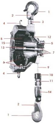
Figure 1. Parts of spring Balancer.
3. Methodology
Figure 2 shows the steps involved in a analysis of hook which is an integral part of spring balancer. It begins with the problem definition. Each and every component is designed and optimum material selection is carried out. Forged hooks are designed according to the nature of weight to be carried and it is assembled to the tapered cable drum with the stranded steel cable. Manual calculation which is carried out is validated with the analysis carried out in Ansys software.
The hooks are drop forged using mild steel material which can withstand 5 ton capacity. Equations given below are the dimensions and the expressions which are used in the design calculations involved in a curved member. Figure 3 shows the front view of the hook and figure 4 shows the section of the hook.
Radius of the neutral axis is given by the equation (1) and the radius of central axis which is the sum of center of gravity of the section and the inner radius is given in equation (2). The eccentricity is calculated by the difference between the radius of central axis and the neutral axis radius given by equation (3). The overall stress in a inner fiber of the curved member is given by the equation (4) and the factor of safety is calculated by the equation (5). The above equations will signify whether the design of a hook can withstand the load of not.
![]() (1)
(1)
![]() (2)
(2)
![]() (3)
(3)
![]() (4)
(4)
![]() (5)
(5)
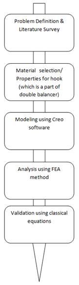
Figure 2. Methodology in design and fabrication of a hook used in double spring balancer.
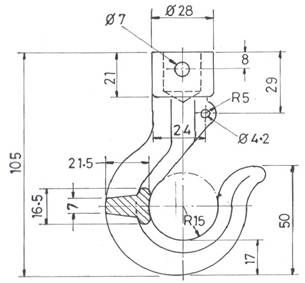
Figure 3. Dimensions of a Hook (All dimensions are in mm).
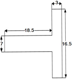
Figure 4. Section of curved beam (All dimensions are in mm).
4. Design and Construction
Working model of double spring balancer consists of various elements. Appropriate design and the material selection hold the key for obtaining the final output. A design of the outer casing body is created with more safety features and a wooden pattern is used in casting process and produces an aluminum body. The outer casing body is shown in the below figure 5. Conical Drum Pulley is designed conical to avoid friction when using the balancer. The spring casing is then attached to the drum pulley to which the wire rope, the shaft and the worm n worm gear are attached. The cone design helps the pulley for better easier rotation with no friction generated. Figure 6 shows the manufactured aluminum pulley by pressure die casting, the slots provided on the pulley are at the place where the wire rope rests. The drum attached to the pulley is a zinc plated spring cover to avoid rusting of the material. The spiral spring mechanism is basically the heart of the balancer. Strips of spring steel is cut into the desired length, this cut spring steel is then bended on the rear ends and using a coiling machine the spring is coiled. This coiled spring which is shown in the figure 7 is then placed in the spring casing for the support and good performance and working of the spring. The casing is also provided with a safety stopper in case there is failure in the spring, it uncoils and pushes the stopper out locking the drum pulley from falling. The centre of the spring is connected to a shaft to which a worm and worm gear is connected for which it used to give tension to the spring. The spiral spring mechanism is used mainly used for contraction and expansion or in other words the vertically up and down movement of the wire rope. The worm gear and worm shaft along with the centre shaft play an important role in tensioning the spring for the amount of load it will be able to carry. The worm gear and the worm shaft is made of EN-8 series of metal and manufactured on the hobbing machine and turning operations. The worm and the worm gear is plated with zinc alloy to avoid rusting of the metal.The worm and worm gear tensioning arrangement is connected to the shaft in a parallel position for when the tension is given to the worm gear by rotating the worm shaft the main shaft rotates giving the spring tension, compressing the spring, for the coil and recoil action. The body is also provided with safety lock mechanism every 2"so as there is any failure in the spring the weight attached to the wire rope will prevent the fall and cause no harm to the user. Design of wire rope and the hook plays a vital role in lifting the weight. Figure 8 shows the very key member of the entire spring balancer that is the forged hook of M.S. material which can withstand around 5 ton capacities.
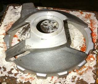
Figure 5. Outer casing body.
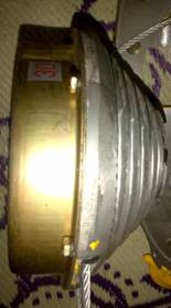
Figure 6. Conical drum pulley.
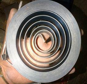
Figure 7. Coiled Spring.
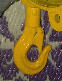
Figure 8. Hook.
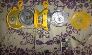
Figure 9. Exploded view of double spring balancer.
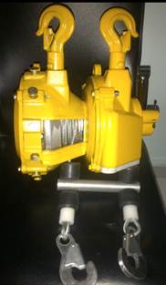
Figure 10. Assembled view of double spring balancer (front view).
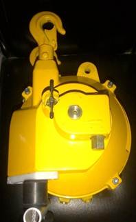
Figure 11. Assembled view of double spring balancer (side view).
Various operations which are involved in the fabrication of the spring balance are Filing, Drilling, Reaming, Hobbing, Grinding, Riveting, Tapping etc. After the body and the other parts are brought to the assembly shop, the assembly of the parts are done and the final product is obtained. Figure 9 shows the exploded view (of the parts) which will be assembled. Initially the pulley is placed in the body 1 to which the cover and body 2 places and the two pulleys are joined with a sliding latch. To which the centre shaft is inserted attaching the spring and the base of the bottom cover. Screws and washers are screwed and the tensioning of the worm and worm gear are done. Figure 10 and figure 11 shows the assembled view of the double spring balancer.
5. Calculation, Testing and Validation
Hook design plays a vital role in the assembly. Curved beam with T section is considered which is used for failure test. Table 1 shows the test results for the curved member which is selected and the results signifies that design of hook is safe.
Table 1. Results obtained with the application of load on curved member.
| Design Parameters of curved beam | Test Result |
| Inner radius (ri) | 15 mm |
| Outer radius (ro) | 36.5 mm |
| Radius of centroid axis (rc) | 22.10 mm |
| Radius of Neutral axis (rn) | 19.4 mm |
| Eccentricity (e) | 2.7 mm |
| Ci= rn-ro | 14.4 mm |
| Co=ro-rn | 21.5 mm |
| Moment (Mb) | 5414.5 N-mm |
| Max stress in inner fiber (σri) | 11.85 MPa |
| Working stress (σ) | 1.36 MPa |
| Factor of safety (σri/σ) | 8.84 |
| Remarks | Satisfactory |
Figure 12 and 13 shows the CREO modeling and the analysis carried out in ANSYS software. The maximum stress acting on the inner fiber of the curved member is 11 MPa which is closer to the theoretical value. Hence results are validated. The above results show that the material which is selected for the design of hook in the double spring balancer is satisfactory. Therefore double spring balancer which is designed carries the desired weight.
Table 2. Force vs stress acting on the inner fiber.
| Sl.No | Mass applied on the curved beam (kg) | Force applied (N) | Stress acting on the inner fiber (σri ) MPa |
| 1 | 20 | 196.20 | 9.70 |
| 2 | 40 | 392.40 | 19.40 |
| 3 | 60 | 588.60 | 29.10 |
| 4 | 80 | 784.80 | 38.80 |
| 5 | 100 | 981.00 | 48.50 |
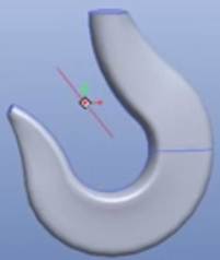
Figure 12. CREO model of hook.
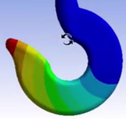
Figure 13. Ansys Analysis of a curved member (hook).
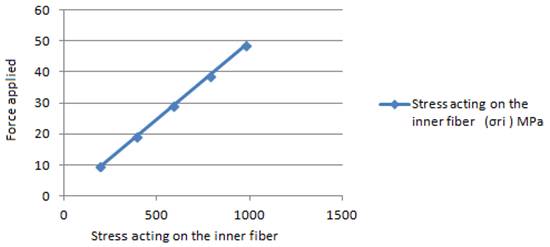
Figure 14. variation of stress acting on inner fiber with the force applied.
6. Conclusion
Current work stress on the critical elements is necessary for lifting the weight. Key elements of the entire set up are stepped pulley, wire rope, spring and hook. Curved member (hook) is modeled in CREO and analyzed in ANSYS software is compared with the theoretical results which is obtained using classical equations. The results show that the stresses acting on the internal fibers in both the cases are similar. T-section which is considered is applied with the load experiences normal stress, shear stress and bending stress which is subjected to the inner fiber of the hook. Ansys analysis shows that the maximum stresses exist at the tip end of the hook. Also from the graph it is concluded that the stress acting on the inner fiber of the hook varies linearly with the force applied. The current design infers that it is safe to lift a weight up to 1000 N. The future work involves generating a three dimensional model of the double spring balancer in a modeling software and exporting it to the Ansys software to apply the loads at the critical points. The system can be automated with the Installation of sensors to the system which will give extra edge in the detection of loads and to obtaining error warnings. With the change in the material overall size and shape can be reduced. Factor of safety can be still reduced to make the system further compact and less weight. With the reduction of the length of centre shaft overall size of the model is reduced. Electronic weight displaying devices can be used in order to measure the weight acting on it.
Nomenclature
A= Area of cross section, mm2
ri= Radius of inner fiber, mm
ro= Radius of outer fiber, mm
rn= Radius of neutral axis, mm
σri= Overall stress in the inner fiber, mm2
e= Eccentricity, mm
F= Applied Force, N
l= Length, mm
Mb= Bending Moment, N-mm
Ci, Co= Constants (obtained with the difference between radius and neutral axis radius) mm
σu= Surface Area, MPa
σ= Normal stress, MPa
b= breadth, mm
FOS= Factor of safety
x= Centroid, mm
References
- Bhasker R.S., Prasad R. K., Kumar V.3, Prasad P, "Simulation of Geometrical Cross-Section for Practical Purposes" International Journal of Engineering Trends and Technology, 2013, Volume4, Issue3. pp: 397-402.
- Yogesh Tripathi & U.K Joshi, "Comparison of stress between winkler-bach theory and ansys finite element method for crane hook with a trapezoidal cross-section" International Journal of Research in Engineering and Technology, 2013,Volume: 02 Issue: 09, pp:26-31
- B Nagaraju,M RajaRoy,P VenkateshReddy ,K Satyanarayana, " Stress analysis of crane hook using FEA" international journal of current engineering and scientific research (ijcesr),2015, volume 2, issue 2, pp: 126-131.
- Chetan N. Benkar & Dr. N. A. Wankhade2,"Finite element stress analysis of crane hook with different cross sections"International Journal For Technological Research In Engineering, 2014 Volume 1, Issue 9, pp: 868-872.
- Sayyedkasim Ali, Harish Kumar, Shishir Agrawal, Milin Kumar Rajurkar, "Stress Analysis of Crane Hook with Different Cross Section Using Finite Element Method"International Journal of Science and Research, 2015, Volume 4 Issue 3,pp: 1954-1956.
- Mr. A. Gopichand, Ms. R.V.S.Lakshm, Mr. B. Maheshkrishna,"optimization of design parameters for crane hook using taguchi method" International Journal of Innovative Research in Science, Engineering and Technology, 2013, Vol. 2, Issue 12,pp: 7780-7784.
- G.R.Dinesh and P.Naveen Chandran,"Analysis of Crane Hook using ANSYS Simulation Tool"International Journal of Advances in Engineering, 2015, vol 1, issue 4, pp: 434-438.
- Tushar Hire & V.N.Bartaria, "Optimum stress analysis of crane hook with the help of finite element analysis" International journal of engineering, education and technology, 2014, volume 2, Issue 2, pp:1-3.
- A Burak Erdil, Derya ozer & Ismail Gerdemeli, "Computer-aided modeling and stress analysis for crane crossheads "'Trends in the Development of Machinery and Associated Technology. 2007, pp: 1003-1006.
- Joseph Leo.A, ArutPranesh.K, Balasubramani.V," Structural analysis of crane hook", International Journal of Emerging Technology in Computer Science & Electronics, 2015, Volume 12 Issue 3, pp: 42-46.


