
International Journal of Energy Science and Engineering, Vol. 1, No. 3, July 2015 Publish Date: Jun. 30, 2015 Pages: 115-125
Investigation of the Influence of Active Material Structure on High Rate Discharge Performance of VRLA Batteries
Alessandro Mariani1, Kary Thanapalan1, *, Jonathan Williams1, Peter Stevenson2
1Centre for Automotive & Power Systems Engineering (CAPSE), Faculty of Computing, Engineering and Science, University of South Wales, Pontypridd, United Kingdom
2Yuasa Battery (UK) Ltd, Rassau Industrial Estate, Ebbw Vale, United Kingdom
Abstract
The following paper presents a simple but effective technique to monitor ageing, deterioration and failure modes of valve regulated lead acid (VRLA) batteries. The investigation primarily deals with high rate discharge products subjected to long standing times in hot environmental conditions, although could be adjusted to products and operating conditions. The technique presented in this paper, was tested and verified by using results obtained from experiments conducted at the YUASA battery laboratories and the CAPSE labs at the University of South Wales (USW). The results indicate that the positive active material was the major cause for low discharge performance with the electrochemical analysis of the battery showing the presence of significant levels of unconverted lead sulphate (5.52 %). Further detailed investigations within this paper also show other key factors that could limit the surface available for the electrolyte to diffuse into the plates, and consequently limit the overall efficiency of the battery. These aspects include the build-up of large lead sulphate crystals, which are difficult to break down in the charge process and may have arisen during the standing time period at high temperature, where the batteries experience accelerated self-discharge.
Keywords
Positive Active Material, Crystal Structure, VRLA Batteries, Failure Mechanism, Estimation Techniques
Received:April 28, 2015
Accepted: May 24, 2015
Published online: June 28, 2015
@ 2015 The Authors. Published by American Institute of Science. This Open Access article is under the CC BY-NC license. http://creativecommons.org/licenses/by-nc/4.0/
Contents
1. Introduction 2. Examination of Different Failure Modes of VRLA Battery 3. Techniques for Estimation 3.1. VRLA Batteries Desirable Features 3.2. Results 3.3. Processes Sulphation of the Positive Active Material 3.4. Experimental Observation 3.5. Failure Mechanism of VRLA Under Higher Power Cycling 4. Conclusions Acknowledgment
1. Introduction
The demand for uninterruptible power supply (UPS) systems is growing substantially in parallel with the technical and economic evolution associated with the growing use of global real time information and communications systems. They are used to protect hardware and electrical equipment’s, providing emergency power to a load when the input power supply fails [1]. This evolving market has driven increased demand for batteries, which have to operate in systems deployed anywhere in the world, where the temperatures and the use of products are diverse [2]. The valve regulated lead acid (VRLA) battery is the most preferable choice for small and medium size UPS energy storage systems for the new market inclination [3-5]. Furthermore, the new market demands for a high rate load discharge applications (typical 10 minutes discharge rate) in hot environmental conditions (35 degree Celsius), is that the long standing times (six months) without compromising the active material crystal structure [7,8]. The operating temperature is also an important factor to be considered because it will affect the efficiency and life of an electrochemical device such as a VRLA battery. It is important to note that heat accelerates the chemical activity; therefore during standing time at high temperature, the VRLA batteries will self-discharge at a high rate, building up internal battery compression due to the formation of large crystals of lead sulphate thickening the plates and squeezing them together [6-9]. Over time, the battery will self-discharge if it is inactive and kept in storage. In a typical room temperature condition (25 degree Celsius), the discharge rate is about 7 to 10% per month. Storage effect degradations and operating temperatures can be considered as the failure modes, which decrease the high discharge rate performance of the batteries [10-15].
In this investigation, firstly, the identification of defective electrode and plate capacity variation are addressed. Secondly, chemical and electrical analysis of discharge positive active material compare with the standard type are analysed. This investigation is may be useful to identify the plate surface areas with lower efficiency to be improved in the design stage. Finally, monitor the microstructure of the positive plates previously selected, to identify the type of crystal structure and the pores size composition to validate the analyses.
2. Examination of Different Failure Modes of VRLA Battery
VRLA batteries that are well maintained and are installed in a properly conditioned environment typically have a service life of 75% of their design life, which is normally about 5 years. High ambient temperature, discharge cycles and charging characteristics are the main factors that affect the life expectancy of a VRLA battery [7,17]. By dissecting and examination of a selection of returned batteries, this investigation identified two main problems:
i). Recharging of the batteries that had significantly different internal resistances has resulted in these mixed states of charge having a Cycling down effect of efficiency of the batteries where they weren’t allowed to rebalance
ii). Discharging of the batteries using inappropriately sized connectors has results in connection points damage through overheating during discharge
The degradation factors over time in the VRLA batteries were identified with the cooperation of many of the end user as well as tests and experiments carried out in CAPSE research labs and YUASA battery laboratories. VRLA batteries were taken from different customers around the world for use in this research. They came from a range of different storage applications and environmental conditions. Records were gathered from the end users to confirm the batteries operational history prior to our research. This was accomplished by taking impedance readings and current float readings on cells in service and open circuit readings on cells that had been taken out of service. The batteries were kept in storage in the warehouse for more than six months without any charge. This caused a modification in the crystal structure of the active material, and consequently compromised their efficiency [8-18].
The tendency issues in this kind of application presented low discharge performance of whole battery installations, rather than individual block problems. The batteries inspected presented mass and thickness within the standard specification, the AGM glass mat was well saturated, and the internal resistance did not present high values to suggest any failure mode. About 60% of VRLA batteries failed due to grid corrosion [17].
The range of temperature where the batteries are installed and the way they are used by customers could affect the VRLA (YUASA) batteries failure mode characteristics [19]. A few cases of low performance batteries were investigated and presented a glass mat which was well saturate with electrolyte, and plate thickness which was within Yuasa specification, but soft positive active material was also evident as shown in Fig 1.
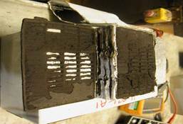
Fig. 1. Typical low performance battery.
Either regular cycling or AC ripple current could be the cause of building up sulphate in the positive plates, and finally breaking down the plate structure. The plate becomes unusable as there are no active sites or chance for the electrolyte to diffuse in or out; consequently the chemical reaction is limited. As mentioned in the introduction, the batteries under investigation used low density positive plates, made with a high percentage of ![]() dioxide type. This kind of crystal morphology is ideal for products that have to deliver high current in a short time, but suffer in hot environmental conditions, reducing their life and efficiency.
dioxide type. This kind of crystal morphology is ideal for products that have to deliver high current in a short time, but suffer in hot environmental conditions, reducing their life and efficiency.
The specific surface area of the positive active material and particle size affect the distribution of the electrolyte available in the pore of the plates. For high load discharge battery applications, a high surface area guarantees good efficiency and product performance. A perfect flat plate shape increases markedly the surface available for the chemical reaction to occur. So the ideal crystal structure for this kind of electrical device, should be composed of ![]() and
and ![]() distributed homogeneously across the plates. If the temperature is still an issue, the battery manufacturer could decide to use an alternative high density plate, but in the initial development stage the designer would have to allow for the extra active material to cover the lowest surface area of the plate.
distributed homogeneously across the plates. If the temperature is still an issue, the battery manufacturer could decide to use an alternative high density plate, but in the initial development stage the designer would have to allow for the extra active material to cover the lowest surface area of the plate.
3. Techniques for Estimation
3.1. VRLA Batteries Desirable Features
VRLA batteries are designed for standby applications, capable of covering cycling requirements, intermitted deep discharges, and able to deliver constant efficiency during their life in extreme temperature (over 35 oC).
The investigation involved examining the following:
1) Cell level. Silver silver reference electrode discharge constant power technique to identify which electrode penalises the performance of the battery.
2) Pellet level. Measure PbSO4 content across different areas of the failed electrode in a discharged condition. Measure total mass of paste remaining in the plate to verify and compare the chemical and electrical performance
3) Crystal level. Scanning electron microscope (SEM) examination of the active material in a charged condition.
Yuasa VRLA SWL2500 series was the batteries type under investigation, standard and low performance devices were made using the same design and manufacture process, tested to achieve the IEC 60896-Part 21 requirements, and passing the safety, performance and durability requirements of IEC 60896-Part 22. Both scenarios performance batteries were tested before dispatched to the customers passing all the Yuasa quality control procedure. They delivered in both cases over 10 minutes discharge time at high rate power (industrial recognize test) ideal choice for uninterruptible power supply (UPS) applications. In the first instance, to discover the reason for low discharge performance duration of the VRLA battery, a single cell reference electrode discharge technique was applied, using Ag2SO4 (silver-silver sulphate reference electrode). The study in this area was conducted to identify which type of electrode failure penalized the battery efficiency. A silver silver sulphate reference electrode discharge was set up, at constant power (2940W to 9.6 V) to a standard and low SWL2500 battery, as shown in Fig. 2.
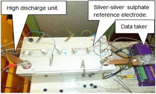
Fig. 2. Single cell reference electrode discharge.
Fig. 3 shows the discharge cells curve of the standard product. The positive and negative electrode maintained the load applied well until the end of the discharge, delivering constant power for 10.29 minutes value within the designed Yuasa construction. The discharge curves of the positive and negative electrodes are represented in the middle and bottom respectively on the graph below.
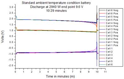
Fig. 3. Ag2SO4 Reference electrode discharge standard product.
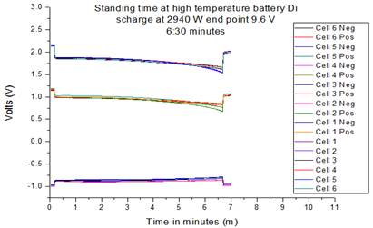
Fig. 4. Ag2SO4 Reference electrode discharge low efficiency product.
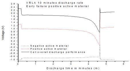
Fig. 5. Ag2SO4 Reference electrode discharge.
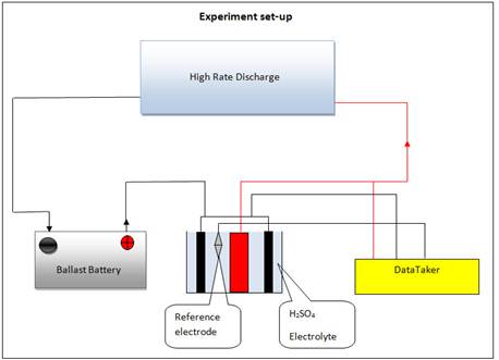
Fig. 6. Test set-up.
Fig. 4 shows that in the low efficient discharge product the battery reached 6.30 minutes value compared to the 10.29 minutes resulted that of the standard product. This was not enough to meet the high standard and the needs of the customers. As can be seen in Fig.4 the positive electrode failed early, and reduced the overall battery discharge efficiency.
The test was repeated several times and the same failure mode is identified as shown in Fig. 5.
From the results obtained; after initial investigation cell 2 from both products was selected. It had 6.30 min and 10.29 min duration for standing time at high temperature and standard product condition respectively (see, Fig. 3 and 4). Using a single plate discharge technique for the Cells selected, it has been observed that each single positive active material discharged is the main failure mode for the battery type under investigation. Batteries and cells were selected to carry on the investigation using reference electrode discharge analysis. An experiment was conducted using the test set-up shown in Fig.6 to discover the core issue that causes the inefficient performance of the VRLA battery. In this experiment a single plate discharge test was carried out using the same reference electrode for all plates to apply on low and standard performance batteries to make future comparison.
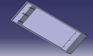
Fig. 7. Single plate discharge prototype.
Thirteen single plate discharge prototypes were created in YUASA battery laboratories using the Catia drawing specification to test a single cell, composed by six positive and seven negative plates as shown in Fig. 7.
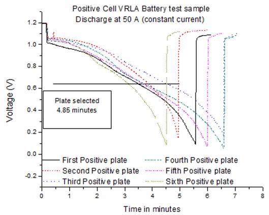
Fig. 8. Single plate discharge low positive cell.
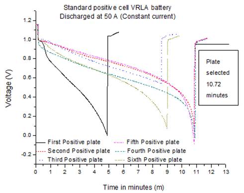
Fig. 9. Single plate discharge standard positive cell.
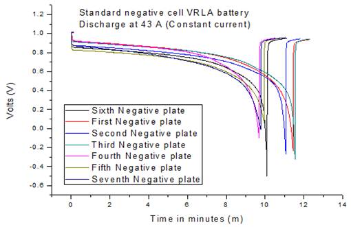
Fig. 10. Single plate discharge standard negative cell.
One positive plate of standard (10.72 minutes high discharge duration) and one of low efficiency product (4.85 minutes high discharge duration) were selected for performance analysis. These were tested for fully analysis: 1) chemistry (% PbSO4 in 9 different areas on the plates selected) and 2) structural SEM (scanning electron microscope analysis) to make comparison of crystal structures and try to understand better the reason for the poorer performance. The discharge performance of the low efficiency battery is shown in Fig.8 with an average of 5.5 minutes, in comparison the standard product performed well with more than 10 minutes average discharge time as shown Fig.9.
The negative electrodes for both standard and low performance batteries were discharged using the same technique. In this case, the rate of discharge was 43A (constant current) because the cell is composed of 7 negative electrodes (300 A/7). As it can be seen in Fig. 10 the negative electrodes from the standard product maintain the discharge rate very well performing overall for 11 minutes.
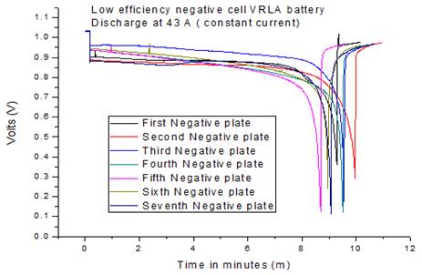
Fig. 11. Single plate discharge low efficiency negative cell.
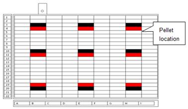
Fig. 12. Grid location.
Fig. 11 shows the discharge performance of the low efficiency negative electrode tested. As can be seen from the graph above, the negative electrodes from the cell performed well; in fact the average discharge time was 9.30 minutes. This factor confirms that the negative electrode was not the cause of the low efficiency discharge performance of the battery under investigation. Plates were taken from the low and standard performance cells for constant current discharge tests. Each plate was discharged at 50Amps until the cell voltage reached 0.1V against to the reference potential. Nine active material pellets were taken from each discharged plate for chemical analysis of their lead sulphate content (Fig. 12). The remaining pellets were removed, washed, dried and weighed to determine the overall mass of active material in each plate
3.2. Results
The Faraday’s principle and lead acid battery double sulphate theory were used to analyse the results. The calculations are used to monitor the performance of the electrode plates under investigation and the dispersion of electrochemical activity across the plate. Two different examples are shown; for standard performance plates and low performance plates showing the electrical and chemical performance of such plates.
Two moles of electrons are transferred during the electrochemical process
![]() (1)
(1)
The electrical capacity equivalent to the observed quantity of PbSO4 was calculated as:
![]() (2)
(2)
Where:
1 mole = 96485 Coulomb (Faraday constant)
C = Coulomb (SI unit of charge)
Amp = ![]() (SI unit of current)
(SI unit of current)
1 Ah = ![]()
It represents the chemical performance in Ah of the average measured 9 PAM samples. The mole of PbSO4 was found dividing the amount of lead sulphate over the atomic weight (303).
The electrical capacity actually measured during the discharge test was found as:
![]() (3)
(3)
The original quantity of PbSO4 in a charged condition for the positive electrode tested is representative of the difference between the chemical equivalent capacity of the PbSO4 in the discharged plate and the actual electrical discharge indicated. Table I summarises the main test results.
Table I. Comparison between standard and test plate.
| Test plate | Standard plate | |
| Sample weight | 202g | 211g |
| %PbSO4 | 16.82 | 25.6 |
| Mole of PbSO4 | 0.11213 | 0.1782270 |
| Chemical performance | 6.01 Ah | 9.555 Ah |
| Electrical performance | 4.04 Ah | 8.93 Ah |
| Perceptual of PbSO4 already in the plate | 5.52% | 1.67% |
Table II shows the % PbSO4 in the samples analyzed in a discharge condition. The difference between chemical and electrical performance in the standard product is reasonable (1.67%), while in the test battery the initial perceptual of sulphate before discharge is quite high (5.52%), it could mean that in the low product, the crystal sulphate structure is bigger and harder to dissolved by the charge process and thus limits the capacity of the positive active material.
Table II. Mathematical and chemical technique results.
| Pellets location across the plate under investigation | Test performance Discharge duration @50 A constant current: 4.85 minutes Cell 2, second positive % PbSO4 | Standard battery Discharge duration @50 A constant current: 10.72 minutes Cell 2, second positive % PbSO4 |
| B3 | 15.29 | 20.27 |
| E3 | 16.60 | 13.46 |
| H3 | 14.18 | 26.40 |
| B10 | 23.00 | 31.00 |
| E10 | 18.44 | 31.00 |
| H10 | 21.67 | 28.70 |
| B20 | 35.00 | 37.80 |
| E20 | 37.90 | 37.00 |
| H20 | 33.96 | 33.30 |
| Chemical average | 16.82 | 25.60 |
| Chemistry performance in Ah | 6.01 | 9.555 |
| Electrical performance in Ah | 4.04 | 8.93 |
| Calculated value for initial % PbSO4 before discharge | 5.52 | 1.67 |
Nine pellets were collected from different areas of a cell (black box in Fig. 12), before the cell was tested using the single plate discharge technique, in a charge condition. These samples were analysed using a scanning electron microscope (SEM). The SEM image in Fig. 13 is from the standard battery tested. The positive active material presents a small and not compact crystal structure, which suggests a good porosity and consequently high electrolyte diffusion and standard performance.
The SEM image in Fig.14 is from the low performance product and present a different scenario, big and compact crystals structure, this could be the cause of low discharge performance due to poor electrolyte diffusion.
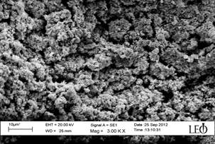
Fig. 13. SEM high efficiency positive active material.
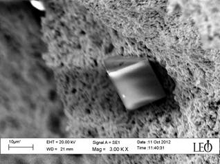
Fig. 14. SEM low efficiency positive active material.
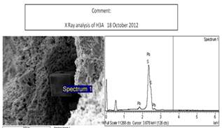
Fig. 15. X-Ray analysis
The main component of a typical VRLA battery type are illustrated in Fig.5. The X-Ray analysis on the low performance positive active material under investigation, confirmed the presence of lead sulphate in a charged state as shown in Fig.15
3.3. Processes Sulphation of the Positive Active Material
The solubility of lead sulphate crystals depends on their size, the bigger the crystals, the less soluble they are. Initially, the concentration of ![]() molecules in the solution is high due to the high solubility of the small sulphate crystals, but this decreases rapidly as a result of the recrystallization process. The equilibrium concentration of
molecules in the solution is high due to the high solubility of the small sulphate crystals, but this decreases rapidly as a result of the recrystallization process. The equilibrium concentration of ![]() ions in the solution is determined by the Ostwald Freundlich [20] equation:
ions in the solution is determined by the Ostwald Freundlich [20] equation:
![]() (4)
(4)
Where: ![]() is the
is the ![]() ion concentration over the small
ion concentration over the small ![]() crystals,
crystals, ![]() is the
is the ![]() ion concentration over the big
ion concentration over the big ![]() crystals, K is a constant, T is the temperature; r is the radius of
crystals, K is a constant, T is the temperature; r is the radius of ![]() crystals.
crystals.
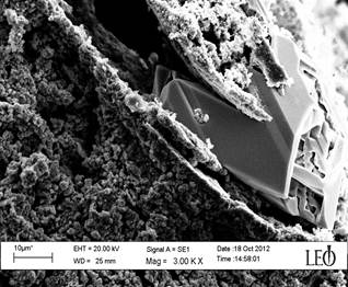
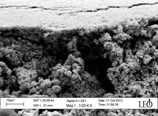
Fig. 16. SEM low efficiency positive active material.
Ostwald Freundlich, and Arrhenius equations explain the change in ![]() positive active material crystals structure associated with standing time and temperature fluctuation [6,2]. The low discharge performance of the products under investigation, have suffered from significant recrystallization due to the temperature change during the standing time and a lead sulphate crystal structure with large and non-homogenous crystals has formed the failure mechanism of VRLA under higher power cycling. Other batteries with the same history were analysed and it confirmed the same scenario. There was no homogenous crystal structure in the positive active material and there was a presence of lead sulphate not converted to lead dioxide during the charge process as shown in Fig. 16.
positive active material crystals structure associated with standing time and temperature fluctuation [6,2]. The low discharge performance of the products under investigation, have suffered from significant recrystallization due to the temperature change during the standing time and a lead sulphate crystal structure with large and non-homogenous crystals has formed the failure mechanism of VRLA under higher power cycling. Other batteries with the same history were analysed and it confirmed the same scenario. There was no homogenous crystal structure in the positive active material and there was a presence of lead sulphate not converted to lead dioxide during the charge process as shown in Fig. 16.
For lead acid batteries that have to support high discharge load application in hot environmental conditions, it is suggested to use a different paste density that can support a higher temperature charge.
3.4. Experimental Observation
The presence of large and hard lead sulphate crystals, in charged condition, decreased the conductivity of the active material, increasing the electrical resistance of the battery. This investigation demonstrate in detail that the electrical study at battery cell and plate level, alongside chemical study, identify the location of the plate problem, and microstructure analysis to define good and bad condition scenario efficiency.
3.5. Failure Mechanism of VRLA Under Higher Power Cycling
In high power discharge rate applications, the chemical reactions between the active material and the electrolyte takes place within the pores, but the rate of the reactions is too fast for a significant quantity of strong electrolyte from the reservoir of the absorptive Glass-mat (AGM) separator to diffuse into the pores of the active material. This is the major limitation in performance at high discharge rate in VRLA batteries, so the tendency is to use plate made with low density active material to increase the plate surface area and thus increase the electrolyte available during discharge. Furthermore, through this investigation, it has been identified that it is possible to improve many older VRLA products by for example, retrofitting with an internal catalyst to maintain the charge level and therefore the performance of the negative plates and the battery, while reducing the secondary evolution of hydrogen due to chemical reactions at the negative plates. The corresponding reduction of the polarization on the positive plates results in a lower rate of positive plate corrosion and therefore longer life.
4. Conclusions
In this paper an effective technique for estimating the VRLA batteries ageing, degradation and failure modes is described. Initial application of the technique has shown verifiable results described below:
High temperature operating conditions and long standing time in a warehouse without any charge increases the stress on the active material and the rate of self-discharge by changing the initial material structure to larger less homogenous crystal design that becomes more compact and less capable of holding the electrolyte on place. These factors have been validated by performing various tests and experiments in Yuasa battery laboratories and CAPSE labs at the University of South Wales.
The single cell and single plate reference electrode discharge technique detected that the positive active materials are the major cause for the low discharge performance of the batteries tested. The electrical and chemical analysis shows the presence of 5.52 % lead sulphate in a charged condition and that could limit the active material available to accept current, thus bring down the efficiency. Furthermore, it presented a very compact surface with a large crystal structure, co validated by SEM images and X-ray analysis that would limit the diffusion process and might be limited by the electrochemical reactions especially at high rate current.
Current research is on-going to assess the true quality of the technique described in this paper. In addition further investigation will be carried out to use and develop a simulation model for battery design to fit specific environmental and operational condition.
Acknowledgment
The first author would like to acknowledge the financial support from the Knowledge Economy Skills Scholarships (KESS), Yuasa Battery (UK) Ltd and the University of South Wales (USW) during this research project. The authors would also like to thank the staff of the Centre for Automotive and Power Systems Engineering (CAPSE) for their assistance.
References
- Bitterlin IF (2004) Standby-battery autonomy versus power quality. J. of Power Sources 136 (2): 351-355.
- Stephen D (1999) TheModel, Methods of Measurement, and Application of Chemical Reaction Codes. United States Environmental Protection Agency 1: 1-212.
- Pascoe P E, Anbuky A H (2004) VRLA battery discharge reserve time estimation. IEEE Trans on Power Electronics 19 (6): 1515–1522.
- Sun YH, Jou HL, Wu JC (2007) Novel Auxiliary Diagnosis Method for State-of-Health of Lead-Acid Battery. 7th International Conf. on Power Electronics and Drive Systems: 262–266.
- Culpin B (1995) Separator design for valve-regulated lead/acid batteries. J Power Sourc 53 (9): 127-135.
- Vinal GW (1951) Storage Batteries: a general treatise on the physics and chemistry of secondary batteries and their engineering application. (Wiley & sons, 1951, 4th Ed, 1500)
- Sun YH, Jou HL, Wu JC (2008) Intelligent Aging Estimation Method for Lead-Acid Battery. In Eighth International Conference on Intelligent Systems Design and Applications, January 2008: 251–256.
- Stevenson PR (2003) Advanced separator construction for long life valve-regulated lead-acid batteries. J Power Sourc 53 (116): 160-166.
- Pascoe P E, Anbuky AH (2000) VRLA battery capacity estimation using soft computing analysis of the coup de fouet region. Telecommunications Energy Conference: 589–596.
- Esperilla JJ, Felez J, Romeo G, Carretero A (2007) A full model for simulation of the elertochemical cells including complex behavior. J Power Sourc 165 (1): 436-445.
- Huang T, Ou W, Feng B, Huang B, Liu M, Zhao W, Guo Y (2012) Researched on current distribution and plate conductivity of valve-regulated lead acid batteries. J Power Sourc 210: 7-14.
- Mauracher P, Karden E (1997) Dynamic modelling of lead/acid batteries using impedance spectroscopy for parameter identification. J Power Sourc 67 (1-2): 69-84.
- Lawrence EL, Ball RJ, Evans R, Stevens R (2002) Effect of soaking time on the positive active material and performance of the valve regulates lead/acid battery. J Power Sourc 110 (1): 125-132.
- Weighall MJ (2001) Keeping up the pressure, strategy to maintain plate-group pressure and extend the cycle life of VRLA batteries. J Power Sourc 95 (1): 209-217.
- Dayton TC (2000) Improving the performance of a high power, lead–acid battery withpaste additives. J Power Sourc 85 (1): 137-144.
- Pascoe PE, Anbuky AH (2004) A unified discharge voltage characteristic for VRLA battery capacity and reserve time estimation. Energy Conversion and Management 45 (2): 277–302.
- Picciano N (2007) Battery Aging and Characterization of Nickel Metal Hydride and Lead-Acid Batteries. PhD Dissertation, The Ohio State University.
- Yan JH (2004) Failure mechanism of valve-regulated lead-acid batteries under high-power cycling. J Power Sourc 133 (1): 135-140.
- MarianiA,Thanapalan K, Stevenson P, Williams J (2013) Techniques for Estimating the VRLA Batteries Ageing, Degradation and Failure Modes. In 19th International Conf. on Automation and Computing, London, UK, September 2013: 43 – 47.
- Pavlov, D., Nikolov, P.:’Capacitive carbon and electrochemical lead electrode systems at the negative plates of lead-acid batteries and elementary processes on cycling’,J. of Power Sources, 2013, (242), pp. 380-399.


