
International Journal of Energy Science and Engineering, Vol. 1, No. 2, May 2015 Publish Date: Apr. 22, 2015 Pages: 49-59
Heat-Mass Transfer in a Tubular Chemical Reactor
Rehena Nasrin*
Department of Mathematics, Bangladesh University of Engineering& Technology, Dhaka-1000, Bangladesh
Abstract
This paper analyzes numerically the effect of double-diffusive forced convection of fluid in a tubular chemical reactor. The model provides a study of an elementary, exothermic, 2nd-order reversible reaction in a tubular reactor (liquid phase, laminar flow regime). The aim of this project is to study numerically the effect of convective Heat and Mass transfer flow of a viscous fluid in the reactor. Assuming that the variations in angular direction around the central axis are negligible makes it possible to reduce the model to a 2D axisymmetric model. The governing equations namely mass, momentum, energy and material conservation equations are solved by Finite Element Method using Galerkin’s weighted residual scheme. The effects of rate of reaction and heat of reaction on the flow pattern and heat and mass transfer have been depicted. Comprehensive average Nusselt and Sherwood numbers, average temperature and concentration and mean subdomain velocity of the tubular reactor are presented as functions of the governing parameters mentioned above. Code validation is also shown with the results available in the literature.
Keywords
Tubular Reactor, Heat-Mass Transfer, Finite Element Method
Received: March 28, 2015
Accepted: April 11, 2015
Published online: April 20, 2015
@ 2015 The Authors. Published by American Institute of Science. This Open Access article is under the CC BY-NC license. http://creativecommons.org/licenses/by-nc/4.0/
Contents
1. Introduction 2. Physical Configuration 2.1. Mathematical Formulation 2.2. Average Nusselt and Sherwood Numbers 2.3. Mean Bulk Temperature, Concentration and Velocity 3. Finite Element Formulation and Computational Procedure 3.1. Grid Refinement Check 3.2. Mesh Generation 3.3. Code Validation 4. Result and Discussions 4.1. Effect of Rate of Reaction (R) 4.2. Effect of Heat of Reaction (H) 5. Conclusion Acknowledgements Nomenclature
1. Introduction
Few researchers investigated the effects of forced convective flows in tubular chemical reactor by using analytical, experimental and numerical methods. Some important works are presented below.
Combined heat and mass transfer from a horizontal channel with an open cavity heated from below is numerically examined Brown and Lai [1]. Parvin et al. [2] analyzed numerically the effect of double-diffusive natural convection of a water–Al2O3 nanofluid in a partially heated enclosure with Soret and Dufour coefficients. Muthucumaraswamy and Ganesan [3] studied effect of the chemical reaction and injection on flow characteristics in an unsteady upward motion of an isothermal plate. Deka et al. [4] studied the effect of the first order homogeneous chemical reaction on the process of an unsteady flow past an infinite vertical plate with a constant heat and mass transfer. Chamkha [5] studied the MHD flow of a numerical of uniformly stretched vertical permeable surface in the presence of heat generation/absorption and a chemical reaction. He assumed that the plate is embedded in a uniform porous medium and moves with a constant velocity in the flow direction in the presence of a transverse magnetic field.
Ibrahim et al. [6] have studied the effect of chemical reaction and radiation absorption on the unsteady MHD free convection flow past a semi infinite vertical permeable moving plate with heat source and suction. Kesavaiah et al. [7] have studied the effect of the chemical reaction and radiation absorption on an unsteady MHD convective heat and mass transfer flow past a semi-infinite vertical permeable moving plate embedded in a porous medium with heat source and suction. Heat and mass transport in tubular packed reactors at reacting and non-reacting conditions was analyzed by Koning [8] where the most common models of wall-cooled tubular packed bed reactors were presented. The two dimensional axial plug flow model was used for a water gas shift reactor to compare heat conduction or mass diffusion with convective effect. Heat and mass transfer in tubular reactor is shown in [9-10]. The two dimensional axial plug flow model was used for a water gas shift reactor to compare heat conduction or mass diffusion with convective effect in his study.
The design of catalyst particles for fixed-bed reactor is optimized by computational fluid dynamics (CFD). The CFD is used to obtain detailed flow and temperature fields in the reactor. In the field of reactor engineering, physical demands such as low pressure drop or high heat transfer efficiency are often in conflict with chemical demands such as gas contact efficiency [11]. Low tube-to-particle diameter ratio is needed for heat management, i.e. sufficient heat supply from the reactor wall for highly endothermic reaction or sufficient heat removal to the reactor wall for highly exothermic reaction [12]. Steam reforming of hydrocarbons is one of the examples, which is an endothermic reaction [13], while another is CO combustion, which is an exothermic reaction.
The early stage of reactor modelling has been based on simplifying assumption such as homogeneity, effective transport parameters, and pellet effectiveness factors [14,15]. Homogeneity stands for viewing the fixed-bed as a single phase continuum. The assumption of effective or apparent transport parameters is based on the idea of unidirectional axial plug flow of the fluid throughout the reactor. These effective transport parameters are determined empirically, i.e. the parameters lump together all of the contributing physical phenomena. This assumption is still employed frequently in reactor modelling [16-18]. However, this approach has always caused inconsistency in the heat transfer coefficient or wall Nusselt number among a number of reported results. The inconsistency is originated from the lack of the local-scale flow picture of the bed. Recent magnetic resonance imaging (MRI) [19] have demonstrated that heat is transferred not solely by axial flow but also by strong radial convective flows as fluid is displaced around the packing elements.
Masoumi et al. [20] developed a 1D steady-state model for tubular reactors in naphtha cracking. A free-radical reaction scheme including 90 species and 543 reactions was used. An optimization study was performed with the aim to maximize operating. Computational techniques for fluid flow have recently employed for reactor modelling as an alternative method to the above mentioned semi-empirical method, in attempting to understand detailed flow in the pore scale. The approach was validated by comparing apparent transport parameters with those from model-matching theory based on experimental measurements [21,22]. One of the outcomes of CFD is a complex picture of strong radial flow. Local heat transfer rates were shown not to be correlated statistically with the local flow field [23]. The pressure and the wall temperature were found to have little or no influence on the apparent heat transfer parameters [24]. One of the concerns in CFD is that all elements have a finite dimension in all edges, which does not allow actual contact points between solid parts. This limitation causes inconsistency of heat transfer coefficient with the one calculated by model-matching theory. To avoid this, the diameter of the particles was slightly reduced in the model and finer mesh density was applied to wall-particle and particle-particle contact regions [25]. Very recently, semi-empirical relation for forced convective analysis through a solar collector was studied by Nasrin and Alim [26].
In the light of above discussions, it is seen that there has been a good number of works in the field of heat and mass transfer system through chemical reactor. In spite of that there is some scope to work with fluid flow, heat-mass transfer and enhancement of reactor efficiency especially for tubular reactor.
The knowledge of forced convection heat transfer has many significant engineering applications; for example, geothermal engineering, solar-collectors, cold storage performance, thermal insulation of buildings, chemical reactors, electrical, microelectronic equipments containers and in many other design problems convective heat transfer is predominant. Therefore the analysis of the heat-mass transfer through a tubular reactor is necessary to ensure better performance of production. This forms the basis of the motivation behind selecting the present research.
2. Physical Configuration
The model geometry of tubular reactor is given in the figure 1. This model consists of an inlet boundary,an outlet boundary, a reactor wall facing the cooling jacket, a cooling jacket, and a symmetry line running axially along the tubular reactor.
Assuming that the variations in angular direction around the central axis are negligible makes it possible to reduce the model to a 2D axisymmetric model. A schematic diagram of the system considered in the present research is shown in the figure 2. In this study, an axial two dimensional tubular reactor model is built up numerically using software.Land Ra are the length and radius of the reactor.Only steady state case is considered.
2.1. Mathematical Formulation
This example provides astudy of an elementary, exothermic, second order reversible reaction
in a tubular reactor (liquid phase, laminar flow regime). The reactor is equipped with a cooling jacket to limit the temperature increase due to the exothermic nature of the reaction and avoid an explosion. The model is described by the mass and momentum balances for the laminar flow region, material balances for the species involved and the energy balances for the reactor and the cooling jacket.
Assuming that the diffusivity for the three species is identical, thereactor can be modeled using six differential equations; one mass balance and two momentum balances for laminar flow, one material balance for one of the species, one energy balance for the reactor core, and one energy balance for the heating jacket. Due to rotational symmetry, only the solution of these equations is obtained for half of the domain shown in the figure 2.
The mass balance, momentum balances, material balances and energy balances in the tubular reactor can be represented with partialdifferential equations (PDEs), while one ordinary differential equation (ODE) is required for the energy balance in the cooling jacket.
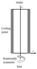
Figure 1. Geometry for 2D rotationally symmetric model of tubular reactor.
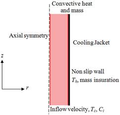
Figure 2. Schematic diagram of the tubular reactor.
The material balance and the energy balance in the reactor are defined in the governing equationswhile the ordinary differential equation describes the energy balance in the cooling jacket is defined as a boundary equation.
The mass, momentum, energy and material balances for the tubular reactor can be described by:
Mass Conservation Equation:
![]() (1)
(1)
Momentum Conservation Equations:
 (2)
(2)
 (3)
(3)
Energy Conservation Equation:
 (4)
(4)
Material Conservation Equation:
![]() (5)
(5)
Here![]() is the rate of reaction,
is the rate of reaction,  is the heat of reaction,
 ![]() is Prandtl number and
is Prandtl number and ![]() is the Reynolds number.
is the Reynolds number.
The boundary condition also simulated the actual reaction condition. Figure 2 shows the boundary conditions for velocity, temperature, and CO concentration. The inlet gas composition was set to 13%CO-8%CO2- 28%H2O- 51%H2, which corresponds to 2.542 mol/m3 of CO concentration. The fluid velocity at inlet is assumed laminar flow with average velocity of 0.085 m/s.
The boundary conditions are:
at the inlet: vr = 0, vz = vin, T =Tin, c = Cin
at the outlet: convective heat and mass boundary condition
at the right wall: non slip condition, T =Th, mass insuration condition
at the left wall: axial symmetry condition.
The effect of water gas shift reaction was included in heat and mass transfer. However, the total molar amount of the gas was assumed constant, i.e. the fluid was assumed to be ideal gas, so that the equation of momentum balance is independent of those of heat and mass transfer. This assumption also simplifies the calculation of mass, i.e. only CO concentration is needed for consideration. The rate expression of water gas shift was based on Arrhenius equation as shown below. The reaction orders for reactants and products were obtained from literature. The term of approach to equilibrium, β, was introduced so that it counts suppression of the reaction rate in the CO concentration range close to equilibrium. Although reaction orders, activation energy, pre-exponential factor are affected by temperature or mass concentration, they were assumed constant for simplification. Nonetheless, this rate expression realizes mutual interaction between heat and mass balance.
Water gas shift reaction: CO + H2O = CO2 + H2
R (rate) = dc(CO)/dt = - Aexp(-Ea/GcT) aCO0.1aH2O0.8aCO2-0.2aH2-0.6(1-β)
β = (aCO2 aH2) / (aCO aH2O) K
Where A is pre-exponential factor for the reaction rate, Ea is activation energy and Gc is gas constant.
Only axial temperature variations may present in the cooling jacket and the flow eliminates any temperature differences in the radial direction. This assumption gives a single ODE for the energy balance:
![]() (6)
(6)
where Ta is the coolants’ temperature, mc is the mass flow rate of the coolant, Cpc represents its heat capacity, and Uk is the total heat-transfer coefficient between the reactor and the cooling jacket. The contribution of heat conduction in the cooling jacket is neglected and thus it is assumed that heat transport takes place only through convection.
As a boundary condition the temperature of the incoming cooling fluid:
![]()
2.2. Average Nusselt and Sherwood Numbers
The average Nusselt number (Nu) is expected to depend on a number of factors such as thermal conductivity, heat capacitance, viscosity and flow structure. The rate of heat transfer along the right heated wall of the tubular reactor is ![]() and rate of mass transfer along the inlet opening is
and rate of mass transfer along the inlet opening is  Where S is the non-dimensional length of the heated/contaminant surface. Non-dimensional quantities are:
2.3. Mean Bulk Temperature, Concentration and Velocity
The mean bulk temperature, concentration and magnitude of sub domain velocity of the fluid inside the tubular reactor can bewritten as![]() ,
, ![]() ,
, ![]() ,
,
where ![]() is the volume of the tubular chemical reactor.
is the volume of the tubular chemical reactor.
3. Finite Element Formulation and Computational Procedure
The governing equations along with the boundary conditions are solved numerically, employing Galerkin weighted residual finite element techniques. To derive the finite element equations, the method of weighted residuals [27-29]is applied to the governing equations (1) – (5). Gauss’s Divergence theorem is applied to transfer the 2nd ordered derivative part of the governing equations into 1st order derivatives. Gaussian quadrature technique is used in momentum, energy and concentration equations in order to generate the boundary integral terms associated with the surface tractions, heat flux and concentration flux. The basic unknowns for the above differential equations are the velocity components vr, vz, the temperature T,the concentration c and the pressure p. The six node triangular element is used in this work for the development of the finite element equations. All six nodes are associated with velocities, temperature as well as concentration. Only the corner nodes are associated with pressure. This means that a lower order polynomial is chosen for pressure and which is satisfied through continuity equation. The element matrices are evaluated in closed form ready for numerical simulation. Substituting the element velocity components, the temperature, the concentration and the pressure distributions to the governing equations the linear algebraic equations are obtained. Then the equations are solved by applying the Newton-Raphson iteration technique. This leads to a set of algebraic equations with the incremental unknowns of the element nodal velocity components, temperatures, concentration and pressures.The iteration process is terminated if the percentage of the overall change compared to the previous iteration is less than the specified value.To solve the sets of the global nonlinear algebraic equations in the form of matrix, the Newton-Raphson iteration technique has been adapted through PDE solver with MATLAB interface. The convergence of solutions is assumed when the relative error for each variable between consecutive iterations is recorded below the convergence criterion ε such that ![]() , where n is number of iteration and
, where n is number of iteration and ![]() and p. The convergence criterion was set to ε = 10-6.
and p. The convergence criterion was set to ε = 10-6.
3.1. Grid Refinement Check
An extensive mesh testing procedure is conducted to guarantee a grid-independent solution for Re = 1.5, Pr = 7, H = 1and R = 1 through the tubular reactor. In the present work, five different non-uniform grid systems are examined with the following number of elements within the resolution field: 86, 170, 506, 2024 and 8096. The numerical scheme is carried out for highly precise key in the Nu and Sh for the aforesaid elements to develop an understanding of the grid fineness as shown in Table 1. The scale of the average Nusselt and Sherwood numbers for 2024 elements shows a little difference with the results obtained for the other elements. Hence, considering the non-uniform grid system of 2024 elements is preferred for the computation.
Table 1. Grid Testat Re = 1.5, Pr = 7, H = 1kJ/mol and R = 1 mol/m3/s.
| Elements | 86 | 170 | 506 | 2024 | 8096 |
| Nu | 6.82945 | 7.23842 | 7.72141 | 8.00183 | 8.00206 |
| Sh | 0.53256 | 0.71475 | 0.92181 | 1.10204 | 1.10275 |
| Time (s) | 126.265 | 312.594 | 398.157 | 481.328 | 929.377 |
3.2. Mesh Generation
In the finite element method, the mesh generation is the technique to subdivide a domain into a set of sub-domains, called finite elements, control volume, etc. The discrete locations are definedby the numerical grid, at which the variables are to be calculated. It is basically a discrete representation of the geometric domain on which the problem is to be solved. The computational domains with irregular geometries by a collection of finite elements make the method a valuable practical tool for the solution of boundary value problems arising in various fields of engineering. Figure3 displays the finite element mesh of the present physical domain.
![]()
Figure 3. Mesh generation of the tubular reactor.
3.3. Code Validation
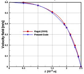
Figure 4. Comparison between present code and Kugai[9].
The present numerical code is validated by comparing the current code results for velocity field – radial distance [r] profile of fluid withthe graphical representation of Kugai [9] at average flow rate 0.4 m/s.Effect of average flow rate on z-velocity is shown in the figure 4. Heat and mass transfer on fixed bed tubular reactor was reported by Kugai [9].Fig. 4 demonstrates the above stated comparison.As shown inthe figure4, the numerical solutions {present work andKugai [9]} are in goodagreement.
Validity of the simulation is also checked by COconcentration at equilibrium constant of 21.34 for reaction temperature (623.15K). CO concentration is calculated to be 0.566 mol/m3, which is consistent with the simulated result.
The maximum Reynolds number (Re) inside the reactor ranged from 0.1 to 2, which indicates the system is stable. Since characteristic mesh length L is around 2 x10⁻⁴ m, estimated Reynolds number (Re) from is 0.4, which is within the range obtained from the simulation. Peclet number (Pe) for mass transfer ranged from 0.1 to 1.5, which is also low enough for the simulation to converge. The estimated Pe from is 0.3, which is also in good agreement with simulation.
Re= ρvL / η and
Pe = vL / D
4. Result and Discussions
Finite element simulation is applied to perform the analysis of laminar forced convection temperature, fluid flow, concentration through a tubular chemical reactor. Effects of the rate of reaction (R) and heat of reaction (H) on heat-mass transfer, fluid velocity through the tubular reactor have been studied. The ranges of R and H for this investigation vary from 1 to 5 and (-400kJ/mol) to (+20kJ/mol) respectively. The outcomes for the different cases are presented in the following sections. Reynolds number (Re = 1.5), Prandtl number (Pr = 7) are kept fixed.
4.1. Effect of Rate of Reaction (R)
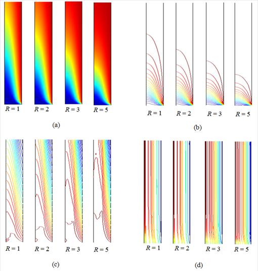
Figure 5. Effect of R on (a) surface plot and (b) isotherms, (c) iso-concentration and (d) streamlines plot.
The effect of rate of chemical reaction (R) on the surface temperature, isotherms, iso-concentrations and streamlines is exhibited inthe figure5 (a-d). In fact, the analysis is performed at forced convection regime by fixing Re= 1.5. Also Pr = 7, H = 1 kJ/mol are kept fixed. The values ofchemical reaction rates 1mol/m3/s, 2mol/m3/s, 3mol/m3/s and 5mol/m3/s are chosen to examine the evolution of surface temperature, isotherm,iso-concentration and streamlinepatterns. Figure 5 (a) expresses that the surface temperature increases due to increasing rate of chemical reaction from 1mol/m3/s to 5mol/m3/s inside the tubular chemical reactor.
The isothermal lines have considerable change due to the variation of R. When there is generating small chemical reaction, lower density of isothermal lines appear at the outlet portion of the channel. But for higher values of rate of chemical reaction, appearance of these lines is more at the outlet opening. It is seen from the figure 5 (b) that, at the highest value of R, the lower temperature lines remain at the inlet opening where as the higher temperature lines at the exit port. Temperature gradient at the right heated surface becomes lower for increasing chemical reaction in the fluid. This happens because higher temperature of the fluid produces lower temperature difference between the heated surface and the fluid.
Figure5 (c) shows the iso-concentration lines which have also substantial change due to generating chemical reaction. Iso-concentration lines spreads all over the tubular chemical reactor. As rate of chemical reaction increases, these lines depart to the exit port. Higher concentration causes lower concentration gradient which indicates lower mass transportation. This phenomenon is logical because generating chemical reaction causes higher velocity which leads to more concentration transfer.
There is a common trend of the development of streamlines with generating chemical reaction inside the computational domain. The streamlines are almost parallel to the channel wall and condensed in axial symmetric region. In addition, the streamlines becomemore condensed along the middle of the tubular reactor due to increasing chemical reaction effect. This indicates higher velocity.
In the Figure6 (i)-(v)average Nusselt number (Nu)at the right hot surface, average Sherwood number (Sh) at the inlet, mean temperature(θav) and concentration (Cav), average velocity (Vav) in the tubular reactor with the effect of chemical reaction. Increasing Rdecreases the value of Nu due to lowering the temperature difference. Heat transfer rate devalues by 23% with the variation of chemical reaction rate R from 1mol/m3/s to 5 mol/m3/s. Similarly, reduced mass transfer rate is observed for increasing the rate of chemical reaction through the tubular chemical reactor.The reduction rate of mass transfer (Sh) is 25%. Average temperature and concentration rise for higher values of R. It is observed from the figure 6 (v) that the average velocity (Vav) increases due to the increase the chemical reaction rate (R).
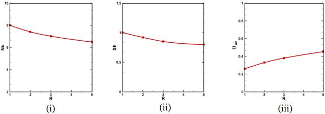
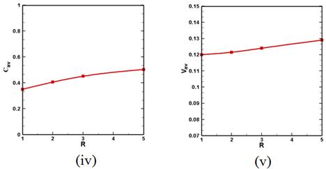
Figure 6. Effect of R on (i) mean Nusselt number, (ii) mean Sherwood number, (iii) mean temperature, (iv) mean concentration and (v) mean velocity.
4.2. Effect of Heat of Reaction (H)
Figure 7 (a-d) exhibits the effect of H on the surface temperature, isotherms, iso-concentrations and streamlines. The values of heat of reaction (H) are -400kJ/mol, -200kJ/mol, 1kJ/mol and 20kJ/mol chosen to examine the evolution of surface temperature, isotherm,iso-concentration and streamline patterns. Heat of reaction (H) is varied from slightly endothermic (+20kJ/mol) to highly exothermic (-400kJ/mol). Here Re = 1.5, Pr = 7, R = 1mol/m3/s are kept fixed.
Figure 7 (a) shows that H does not have much effect on surface temperature. Even the most exothermic reaction increased the surface temperature only by a few degrees. Accordingly, water gas shift reaction is not affected by H.
Isothermal lines have significant change due to the variation of H. At H =(-400kJ/mol), isothermal lines appear at the right hot surface of the tubular reactor. But for higher values of H, these lines spread all over the reactor. It is seen from the figure that, at the highest value of H(= +20kJ/mol), the lower temperature lines remain at the inlet portion where as the higher temperature lines at the right surface. Temperature gradient at the heat source becomes lower for increasing heat generation in the fluid. This happens because higher temperature of the fluid produces lower temperature difference between the hot surface and the fluid.
Iso-concentration lines have also considerable change due to generating heat as shown in the figure 7 (c). Iso-concentration lines spreads all over the tubular chemical reactor. As heat generation increases these lines depart to the exit port which indicates higher mass transportation. This phenomenon is logical because heat generation causes higher velocity which leads to more concentration transfer.
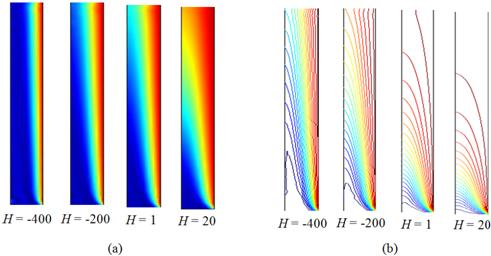
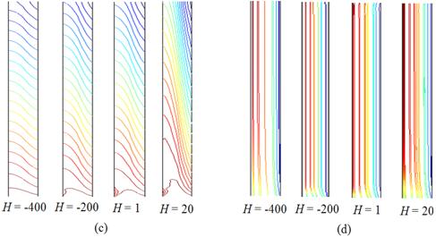
Figure 7. Effect of H on (a) surface plot and (b) isotherms, (c) iso-concentration, and (d) streamlines plot.
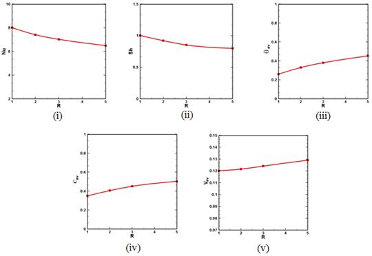
Figure 8. Effect of H on (i) mean Nusselt number, (ii) mean Sherwood number, (iii) mean temperature, (iv) mean concentration and (v) mean velocity.
It is observed from the figure 7 (d) that there is a common trend of the development of streamlines with increasing heat generation parameter. The streamlines are almost parallel to the reactor wall and condensed near the right surface and axial symmetric surface. The streamlines become more condensed along the middle of the channel due to increasing heat generation effect. This indicates higher velocity.
The heat and mass transfer rates, meanbulk temperature and concentration, magnitude of average sub-domain velocity for fluid with the variation of heat of reaction (H) are displayed in the figure8 (i)-(v). It is seen from the figure8 (i) that the highest heat transfer rate is observed for the exothermic flow (H= -400 kJ/mol). Increasing H decreases the value of Nu due to lowering the temperature difference Enhanced mass transfer rate (Sh) is observed in the figure 8 (ii) for decreasing values of heat of reaction (H).For the rate of forced convective heat and mass transfer decrease by 12% and 15% respectively for increasing heat of reaction (H). Mean bulk temperature (θav) and concentration (Cav) grow up slightly for the variation of heat of reaction from (-400kJ/mol) to (+20kJ/mol). On the other hand, figure 8 (v) depicts that Vav rises with the increment of H.
5. Conclusion
The problem of finite element modeling of heat and mass transport in a tubular reactor has been studied numerically. Temperature and concentration and flow fields in terms of surface temperature, isotherms, iso-concentration and streamline have been considered for various heat of reaction and rate of chemical reaction. The present investigation is done for steady-state, incompressible, laminar and forced convective flow through a tubular chemical reactor.The results of the numerical analysis lead to the following conclusions:
• The heat of reaction H has considerable effect on surface temperature, isotherms, iso-concentration and streamlines plots Perturbation is observed in the conductive and convective heat and mass distribution nearby the right hot wall and inlet opening respectively with the variation of H.
• More complicated flow is obtained for the effect of chemical reaction rate R. The thermal current activities of the fluid are found to significantly depend upon R. The temperature and concentration gradient decrease with rising values of chemical reaction rate. Consequently mean velocity enhances.
Acknowledgements
This research work is done in the Department of Mathematics, Bangladesh University of Engineering & Technology, Dhaka-1000. This research is financed by "Information & Communication Technology, Ministry of Science,Bangladesh Computer Council Bhaban, Agargaon, Sher-e-Bangla Nagar, Dhaka-1207.
Nomenclature
| A | Pre-exponential factor |
| c | Dimensional concentration of fluid (kg/l) |
| C | Dimensionless concentration of fluid |
| Cp | Specific heat at constant pressure (J kg -1K -1) |
| Ea | Activation energy (kJ/mol) |
| k | Thermal conductivity of fluid (Wm-1K-1) |
| L | Length of the reactor along z axis (m) |
| H | Heat of reaction (kJ/mol) |
| m | Mass flow rate (Kgs-1) |
| Nu | Average Nusselt number |
| p | Pressure |
| Pe | Peclet number |
| Pr | Prandtl number |
| R | Rate of chemical reaction (mol/m3/s) |
| Re | Reynolds number |
| Sh | Mean Sherwood number |
| T | Fluid temperature (K) |
| vr | Velocity in r-direction (ms -1) |
| vz | Velocity in z-direction (ms -1) |
| V | Magnitude of mean velocity |
|
| Volume of reactor (m3) |
| Greek symbols | |
| a | Thermal diffusivity (m2s -1) |
| θ | Dimensionless fluid temperature |
| μ | Dynamic viscosity of the fluid (m2s-1) |
| ν | Kinematic viscosity of the fluid (m2s-1) |
| r | Density of the fluid (kgm-3) |
| ∆ | Increment |
| Subscripts | |
| av | average |
| in | input |
| h | heated |
| out | output |
References
- Brown, N. and Lai, F., Correlations for combined heat and mass transfer from an open cavity in a horizontal channel, Int. Commun. in Heat and Mass Transf., Vol. 32, No. 8, pp. 1000–1008, 2005.
- Parvin S., Nasrin R., Alim, M.A. and Hossain, N.F., Double-diffusive natural convection in a partially heated enclosure using a nanofluid, Heat Transf. - Asian Res., 41, No. 6, pp 484-497, 2012.
- Muthucumaraswamy, R., Ganesan, P., Effect of the chemical reaction and injection on flow characteristics in an unsteady upward motion of an isothermal plate, J. Appl. Mech. Tech. Phys., Vol. 42, pp. 665-671, 2001.
- Das, U.N., Deka, R., Soundalgekar, V.M., Effects of mass transfer on flow past an impulsively started infinite vertical plate with constant heat flux and chemical reaction, Forsch. in Ingenieurw., Vol. 60, pp. 284-287, 1994.
- Chamka, A.J., MHD flow of a numerical of uniformly stretched vertical permeable surface in the presence of heat generation/absorption and a chemical reaction, Int. Commun. In Heat and Mass Transf., Vol. 30, pp. 413-22, 2003.
- Ibrahim, F.S., Elaiw, A.M., Bakr, A.A., Effect of chemical reaction and radiation absorption on the unsteady MHD free convection flow past a semi infinite vertical permeable moving plate with heat source and suction, Comm. in Nonlinear Sci. and Num. Simul., Vol.13, pp. 1056-1066, 2008.
- Kesavaiah, DC.H., Satyanarayana, P.V. and Venkataramana, S., Effects of the chemical reaction and radiation absorption on an unsteady MHD convective heat and mass transfer flow past a semi-infinite vertical permeable moving plate embedded in a porous medium with heat source and suction. Int. J. of Appl. Math. and Mech., Vol. 7, No. 1, pp. 52-69, 2011.
- Koning, B., Heat and mass transport in tubular packed bed reactors at reacting and non-reacting conditions, Ph.D. Thesis, University of Twente, Netherland, 2002.
- Kugai, J.,Heat and mass transfer in fixed-bed tubular reactor, May 1st 2008, 2008.
- Frolov, S.V., Tret’yakov, A.A. and Nazarov, V.N., Problem of optimal control of monomethylaniline synthesis in a tubular reactor,Theore. Found. of Chem. Engg., Vol. 40, No. 4, pp. 349–356, 2006
- Nijemeisland, M., Dixon, A.G. and Stitt, E.H., Catalyst design by CFD for heat transfer and reaction in steam reforming, Chem. Engg. Sci., Vol. 59, pp. 5185-5191, 2004.
- Rostrup-Nielsen, J.R., Sehested, J.and Norskov, J.K., Hydrogen and synthesis gas by steam- and CO2 reforming, Adv. Catal, Vol. 47, pp. 65-139, 2002.
- Kvamsdal, H.M., Svendsen, H.F., Hertzberg, T.and Olsvik, O., Dynamic simulation and optimization of a catalytic steam reformer, Chem. Engg. Sci., Vol. 54, pp. 2697-2706, 1999.
- Dixon, A.G. and Nijemeisland, M., CFD as a design tool for fixed-bed reactors, Ind. Engg. Chem. Res., Vol. 40, pp. 5246-5254, 2001.
- Dixon, A.G. and Cresswell, D.L. Theoretical prediction of effective heat-transfer parameters in packed-beds, Aiche. J., Vol. 25, pp. 663-676, 1979.
- Bunnell, D.G., Irvin, H.B., Olson, R.W. and Smith, J.M., Effective thermal conductivities in gas-solid systems,Ind. Engg. Chem., Vol. 41, pp. 1977-1981, 1949.
- Nijemeisland, M. and Dixon, A.G., Comparison of CFD simulations to experiment for convective heat transfer in a gas-solid fixed bed, Chem. Engg. J., Vol. 82, pp. 231-246, 2001.
- Dixon, A.G. and Cresswell, D.L., Estimation of heat-transfer parameters in packed-beds from radial temperature profiles - Comment, Chem. Engg. J. Bioch Engg., Vol. 17, pp. 247-248, 1979.
- Gladden, L.F., Recent advances in MRI studies of chemical reactors: ultrafast imaging of multiphase flows, Top Catal., Vol. 24, pp. 19-28, 2003.
- Masoumi, M.E., Sadrameli, S.M., Towfighi, J. and Niaei. A.,Simulation, optimisation and control of a thermal cracking furnace, Energy, Vol. 31, p516–527, 2006.
- Gladden,L.F., Mantle, M.D. Sederman,A.J. and Yuen, E.H.L., Magnetic resonance imaging of single- and two-phase flow in fixed-bed reactors, Appl. Magn. Reson., Vol. 22, pp.201-212, 2002.
- Ziolkowska, I. and Ziolkowski, D., Modelling of gas interstitial velocity radial distribution over cross-section of a tube packed with granular catalyst bed; effects of granule shape and of lateral gas mixing" Chem. Engg. Sci., Vol. 62, pp. 2491-2502, 2007.
- Logtenberg, S.A. and Dixon, A.G., Computational fluid dynamics studies of fixed bed heat transfer, Chem. Engg. Process, Vol. 37, pp. 7-21, 1998.
- Dixon, A.G., Nijemeisland, M.and Stitt, E.H., CFD study of heat transfer near and at the wall of a fixed bed reactor tube: Effect of wall conduction, Ind. Engg. Chem. Res., Vol. 44, pp. 6342-6353, 2005.
- Taskin, M.E., Dixon,A.G. and Stitt, E.H., CFD study of fluid flow and heat transfer in a fixed bed of cylinders, Numer. Heat Transf.-Appl., Vol. 52, pp. 203-218, 2007.
- Nasrin, R. and Alim, M.A.,Semi-empirical relation for forced convective analysis through a solar collector, Solar Energy, Vol. 105, pp. 455-467, 2014.
- Zienkiewicz, O.C. and Taylor, R.L., The finite element method, Fourth Ed., McGraw-Hill, 1991.
- Taylor, C., Hood, P., A numerical solution of the Navier-Stokes equations using finite element technique, Computer and Fluids, Vol. 1, pp. 73–89, 1973.
- Dechaumphai, P., Finite element method in engineering, 2nd ed., Chulalongkorn University Press, Bangkok, 1999.


