
International Journal of Energy Science and Engineering, Vol. 1, No. 3, July 2015 Publish Date: Jun. 13, 2015 Pages: 91-99
Analysis of Direct Torque Controlled Induction Motor Drive System for Better Dynamic Response
Vivek Pahwa1, Naveen Sharma2, *
1Electrical & Electronics Engineering, Haryana College of Technology & Management, Kurukshetra University, Kaithal, India
2Pursuing M. Tech in Electrical & Electronics Engineering, Haryana College of Technology & Management, Kurukshetra University, Kaithal, India
Abstract
This work implements a direct torque control with space vector modulation scheme on a 200hp induction motor using MATLAB/SIMULINK environment for better dynamic response. The scheme is implemented with voltage source inverter. Further, the scheme uses stator flux based calculator and depend only on stator resistance and on no other parameters. Thus, making it a simple scheme, as computational steps and dependence on many machine parameters will be reduced. Further, the result of direct - torque – control scheme have been compared with field - oriented control scheme on the same induction motor, and showing that the results of direct- torque-control are superior / better than field- oriented control. The work embodied in this paper established that direct torque control is better control scheme for induction motor drive system.
Keywords
Induction Machine Drive System, Direct Torque Control, Voltage Source Inverter, Space Vector Modulation, Stator Flux Based Calculator, Field-Oriented Control Scheme
Received:March 26, 2015
Accepted: May 14, 2015
Published online: June 12, 2015
@ 2015 The Authors. Published by American Institute of Science. This Open Access article is under the CC BY-NC license. http://creativecommons.org/licenses/by-nc/4.0/
Contents
1. Introduction 2. Direct Torque Control (DTC) of Induction Machines 3. Mathematical Modelling of Direct Torque Control Drive [13-15] 4. Three-Phase Voltage Source Inverter (VSI) 5. Direct Flux Control 6. Direct Torque Control 7. Switching Table 8. Stator-Flux Based Calculator 9. Result and Discussion 10. Model Simulation Using MATLAB/SIMULINK of FOC & DTC Scheme 10.1. Comparison of Results Obtained from Direct Torque Control and Field-Oriented Control 10.2. Electromagnetic Torque vs. Time 10.3. Stator Phase ‘a’, ‘b’ and ‘c’ Current vs. Time 10.4. Stator ‘q’ and ‘d’ Axis Current vs. Time 10.5. Rotor Phase ‘a’, ‘b’ and ‘c’ Current vs. Time 10.6. Rotor Speed vs. Time 10.7. DC Bus Voltage vs. Time 10.8. Stator ‘q’ and ‘d’ Flux Linkages 10.9. FFT Analysis of Electromagnetic Torque 10.10. FFT Analysis of Stator Current 11. Conclusions and Future Scope of Work 11.1. Conclusions 11.2. Future Scope APPENDIX-A
1. Introduction
The various control strategies have been developed, depending upon how the voltage to frequency ratio method is applied. The control of any drive system can be categorised as steady state control and dynamic state control. Most of control strategies, give good steady- state response but poor dynamic response. The main cause of such poor dynamic response is found to be that the air gap flux linkages deviates from their set values. Till now, the control strategies have utilised the stator phase current magnitude and frequency but not their phases [1-9].
Therefore, this paper attempts to get better dynamic response of induction machine drive system by controlling the magnitude and frequency of stator current as well as their phases using direct torque control scheme [10-12].
2. Direct Torque Control (DTC) of Induction Machines
In direct torque controlled (DTC) induction motor drive, supplied by a voltage sources inverter, it is possible to control directly the stator flux linkages (or rotor flux linkage, or magnetizing flux linkage) and the electromagnetic torque by the selection of optimum inverter switching modes. DTC allows very fast torque responses and flexibility control of an induction machine. It is expected that various DTC drive will be emerges in future. ABB is the first industrial company which has introduced (in 1995) a commercially available direct torque controlled induction motor drive.
3. Mathematical Modelling of Direct Torque Control Drive [13-15]
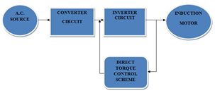
Direct Torque Control (DTC) drives, as shown in Fig. 1 consists of a pair of hysteresis comparator, stator-flux based calculator of three phase Squirrel-cage induction machine, inverter optimal switching table and voltage source inverter (VSI) and a three phase squirrel cage induction motor. In conventional DTC, the stator flux and electromagnetic torque are controlled directly by applying the most appropriate switching state at the VSI. This appropriate switching state are determined by optimum three-dimensional switching table which has an input of the output signal of flux and torque hysteresis comparator and also the position of the flux linkage space vector. By selecting the appropriate VSI switching, the optimum voltage vector can be produced such that the machine’s stator flux and torque are regulated in their respective hysteresis band. Flux and torque estimator has been used to estimate their actual value before being compared and fed into hysteresis comparator.
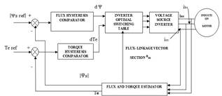
Figure 1. Conventional DTC drive.
4. Three-Phase Voltage Source Inverter (VSI)
The inverter will produce six active voltage vectors (V1, V2 … V6) and two zero voltage vectors (V0, V7). These voltage vectors are shown in Fig. 3.2
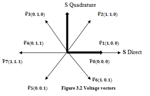
Figure 2. Voltage vectors.
5. Direct Flux Control
Before the selection of the appropriate voltage vectors, the direction or the position of the stator flux had to be known. Therefore, the locus of the flux is divided into several sectors are and due to the six step inverter, the minimum number of sectors required is six, as shown in fig 3. In DTC, stator flux is forced to follow a circular path by a way of limiting its magnitude within its hysteresis band.
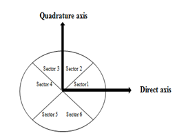
Figure 3. The sector of flux locus.
This can be done by increasing the flux magnitude when it touching the lower limit of the hysteresis band and decreasing it when it touch the upper limit. To know whether the stator flux is needed to be increased or decreased, the relative magnitude of the actual flux compared to the reference flux had to be known. This comparative action can be done by a two level hysteresis comparator as shown in Fig. 4. Flux error status equal to 1 indicates that the stator flux touches its upper band which means that the actual flux needs to be increased and vice versa. Therefore if a stator flux increase is required, then the flux error status d Ψ = 1 and if a stator flux decrease is required, then d Ψ = -1. The resulting digital flux error is based on conditions stated in (1.1) and (1.2).
d Ψ =1 if ![]()
![]()
![]() -
- ![]() (1.1)
(1.1)
d Ψ =0 if ![]()
![]()
![]() +
+ ![]() (1.2)
(1.2)
6. Direct Torque Control
In DTC, at every switching period, the voltage vectors are selected to keep the electromagnetic torque within its hysteresis band. Their torque needs to be reduced when it touches its upper band and increased when it touches it lower band. For this purposes, three levels hysteresis comparator as shown in Fig. 5 has been employed. If a torque increase is required then dTe = 1, if a torque decrease is required then dTe = -1, and if no change in the torque is required then dTe = 0. The dTe is the notation correspond the output signal of three level hysteresis comparator. There are two conditions to be considered. The resulting dTe for anticlockwise rotation (forward direction) and for clockwise rotation (backward rotation) of the stator flux are based on conditions (1.3), (1.4) and (1.5), (1.6) respectively.
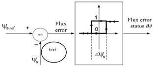
Figure 4. Flux comparator.
dTe = = 1 if ![]() ≤
≤ ![]() -
- ![]() (1.3)
(1.3)
dTe = 0 if ![]()
![]()
![]() (1.4)
(1.4)
dTe = = -1 if ![]()
![]()
![]() +
+ ![]() (1.5)
(1.5)
dTe = 0 if ![]() ≤
≤ ![]() (1.6)
(1.6)
7. Switching Table
The optimum voltage vectors that can satisfy the torque and stator flux demands can be tabulated in a three dimensional look-up table. Table 1 show this look-up table and it can be assessed by stator the flux error status, torque error status and the position of the stator flux.
Table 1. Switching Table for Direct Torque Control.
| dΨs | dTe | θss1 | θss2 | θss3 | θss4 | θss5 | θss6 |
| 1 | 1 | V2 | V3 | V4 | V5 | V6 | V1 |
| 0 | V0 | V7 | V0 | V7 | V0 | V7 | |
| -1 | V6 | V1 | V2 | V3 | V4 | V5 | |
| -1 | 1 | V3 | V4 | V5 | V6 | V1 | V2 |
| 0 | V7 | V0 | V7 | V0 | V7 | V0 | |
| -1 | V5 | V6 | V1 | V2 | V3 | V4 |
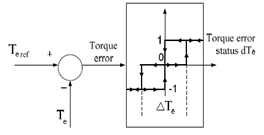
Figure 5. Three-level torque hysteresis comparator.
8. Stator-Flux Based Calculator
The model of three phase squirrel-cage induction machine [1] in arbitrary reference frame is given below;
![]() =
=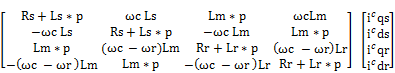 (1.7)
(1.7)
The speed of the reference frame is that of the stator, which is zero; hence,
![]() c =0 (1.8)
c =0 (1.8)
Substitute the equation (1.8) in (1.7) and we get equation (1.9);
![]() =
=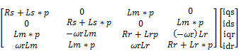 (1.9)
(1.9)
![]() ds =
ds =![]() dt (1.10)
dt (1.10)
![]() qs=
qs=![]() dt (1.11)
dt (1.11)
![]() ᶿfs (1.12)
ᶿfs (1.12)
ᶿfs =![]() (1.13)
(1.13)
Te = ![]()
![]() (
(![]() ds -
ds - ![]() qs) (1.14)
qs) (1.14)
Therefore, the flux linkages, electromagnetic torque computation and angle ᶿfs can be obtained from equation (1.10), (1.11), (1.12), (1.13) and (1.14) respectively. The scheme is also called as stator-flux based calculator as the stator resistance is employed in computation of stator flux linkages.
9. Result and Discussion
Recently, the high performance control of induction motors has been interesting to the researchers in industry, because the induction motor is the most commonly used machine and it advances in power electronics have made possible new control methods. Dynamic numerical simulation is very important to decide whether the new control design processes are valid and to avoid the mistakes early in simulations before actual real implementation. MATLAB/ SIMULINK have been a very powerful tool to model the electrical and the mechanical systems because of its simplicity. Therefore the dynamic simulation of field-oriented control and direct torque control is first performed employing the MATLAB/SIMULINK and then the dynamic performance of is given from figure 1.6.1 to 1.6.9.
10. Model Simulation Using MATLAB/SIMULINK of FOC & DTC Scheme
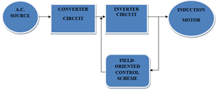
(a)
(b)
Figure 6. (a) Block diagram representation of field-oriented controlled induction Motor Drive system. (b) Block diagram representation of direct torque controlled induction Motor Drive system.
10.1. Comparison of Results Obtained from Direct Torque Control and Field-Oriented Control
10.2. Electromagnetic Torque vs. Time
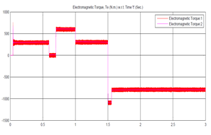
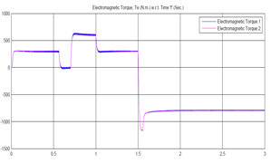
The comparison of figure 7 (a) and (b) shows that at every step change the step changes in torque due to FOC scheme is instantaneously, which is unusual and practically impossible whereas DTC scheme shows instantaneous and smooth response. Further during steady state condition the ripples are very high in FOC scheme in comparison to DTC Scheme.
(a)
(b)
Figure 7. (a) Electromagnetic torque vs. time of field-oriented controlled induction motor drive system. (b) Electromagnetic torque vs. time of direct torque controlled induction motor drive system.
10.3. Stator Phase ‘a’, ‘b’ and ‘c’ Current vs. Time
As seen from figure 8 (a), torque is unable to follow its commanded value at starting, because rotor flux linkages oscillates, resulting in large stator current i.e.3200amps and torque transients. The large stator currents increase the inverter rating to multiple times that of induction motor. This has been reduced significantly to 1250amps using DTC induction motor drive system (refer figure 8(a) and (b)).
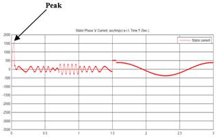
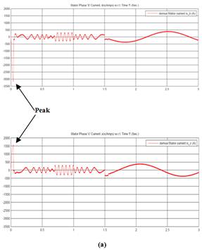
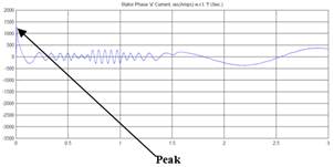
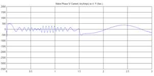
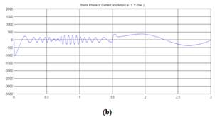
Figure 8. (a) Stator phases ‘a’, ‘b’ and ‘c’ current vs. time of field-oriented controlled induction motor drive system. (b) Stator phase ‘a’, ‘b’ and ‘c’ current vs. time of direct torque controlled induction motor drive system.
10.4. Stator ‘q’ and ‘d’ Axis Current vs. Time
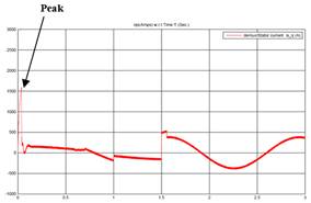
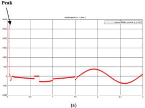
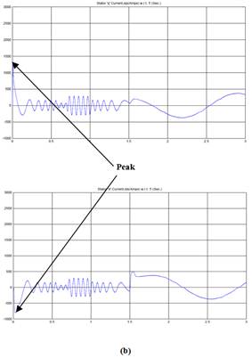
Figure 9. (a) Stator ‘q’ and ‘d’ axis current vs. time of field- oriented controlled Drive system.(b) Stator ‘q’ and ‘d’ axis current vs. time of direct torque controlled Drive system.
As seen from figure 9 (a),the stator quadrature axis current is 1600amps using FOC scheme but this value has been minimize as 1250amps using DTC induction motor drive system(refer figure 9 (b) ).
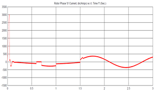
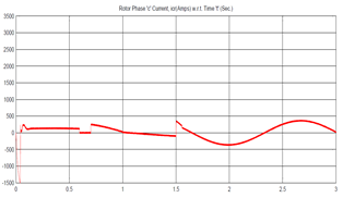
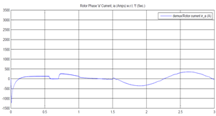
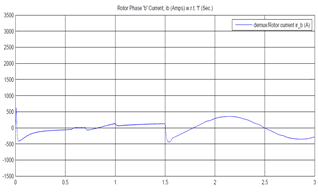
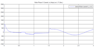
10.5. Rotor Phase ‘a’, ‘b’ and ‘c’ Current vs. Time
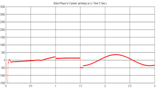
(a)
(b)
Figure 10. (a) Rotor phase ‘a’, ‘b’ and ‘c’ current vs. time of field-oriented controlled induction motor drive system. (b) Rotor phase ‘a’, ‘b’ and ‘c’ current vs. time of direct torque controlled induction motor drive system.
When we start comparison between these two above discussed scheme the value of rotor phase current found drastically increases with 3000amps at 0.1ms using FOC induction motor drive system and value found 750amps at 0.01sec. using DTC induction motor drive system which quit low by using DTC induction motor drive system.(refer figure 10 (a) (b))
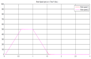
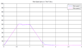
10.6. Rotor Speed vs. Time
(a)
(b)
Figure 11. (a) Rotor speed vs. time of field-oriented controlled induction motor drive system. (b) Rotor speed vs. time of direct torque controlled induction motor drive system.
The comparison of figure 11(a) and (b) shows that;
1. In figure 11(a) i.e. using field-oriented control scheme the rotor speed vs. time graph, it shows that there is delay of 0.1 sec. for starting and get the maximum speed 500 rpm at 0.6 sec. and start dropping the speed drastically at 1.0 sec. and reduced to 0 rpm at 1.6 sec. and after that no rise in speed.
2. But as we studied the rotor speed vs. time graph(refer figure 11(b)), it shows that the no delay in rise in rotor speed and it does not stop instantly i.e. at 1.5 sec. the speed became 60 rpm and starts rising to 80 rpm and then starts dropping with some delay i.e. at 1.8 sec. using direct torque control Scheme.
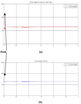
Figure 12. (a) Dc bus voltage vs. time of field-oriented controlled induction motor drive system.(b) Dc bus voltage vs. time of direct torque controlled induction motor drive system.
10.7. DC Bus Voltage vs. Time
For the same starting conditions, the peak voltage is 1200 volts for field-oriented control induction motor drive system (refer figure 12(a)) whereas the peak voltage for DTC induction motor drive system is found to be 900 volts (refer figure 12(b)). Thus, requiring a reduced capacity of converter rating and so does the cost of converter for same operates condition. Further, settling time is reduced drastically from 0.2 ms to 0.02 ms, showing that direct torque control induction motor drive system response time is much faster than field-oriented control induction motor drive system.
10.8. Stator ‘q’ and ‘d’ Flux Linkages
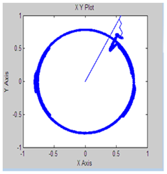
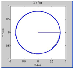
Figure 13. (a) Stator ‘q’ and ‘d’ flux linkages of field-oriented controlled induction motor drive system.(b) Stator ‘q’ and ‘d’ flux linkages of direct torque controlled induction motor drive system.
Figure 13 (a) at starting, the stator flux linkages phasor is not a uniform circle, thus showing that there is no complete decoupling of the flux from torque producing channels. But, figure 13 (b) shows a uniform circle, showing the complete decoupling of flux from torque producing channel due to direct torque control scheme.
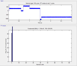
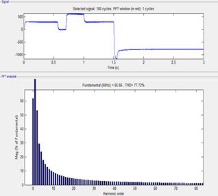
10.9. FFT Analysis of Electromagnetic Torque
(a)
(b)
Figure 14. (a) FFT analysis of electromagnetic torque of field-oriented controlled induction motor drive system. (b) FFT analysis of electromagnetic torque of direct torque controlled induction motor drive system.
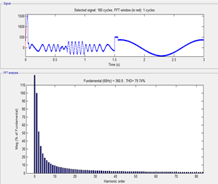
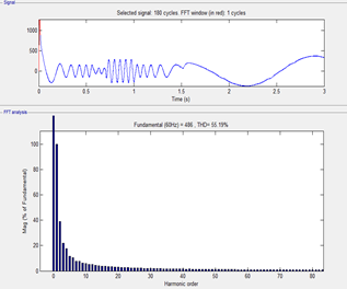
10.10. FFT Analysis of Stator Current
As we seen the FFT analysis to observing the harmonics in electromagnetic torque of both of schemes. (Refer figure no. 15(a) & (b) it is evident that approximately 200% harmonics drastically increases using FOC induction motor drive system as compare to direct torque controlled induction motor drive system and harmonics in stator current is increases 20%(approximately) in case of field-oriented control induction motor drive system which can be shown in figure no. 15 (a) & (b). So these adverse features of harmonics in stator current and electromagnetic torque by using field-oriented control induction motor drive system may sever damage to the induction motor drive system.
(a)
(b)
Figure 15. (a) FFT analysis of Stator Current of field-oriented controlled induction motor drive system.(b) FFT analysis of Stator Current of direct torque controlled induction motor drive system.
11. Conclusions and Future Scope of Work
11.1. Conclusions
By comparing field oriented control scheme and direct torque control scheme of induction machine drive system following conclusions are arrived at:
1. By using / applying direct torque control on induction machine, very precise torque control is achieved [refer figure no. 7(b)] which is the essential requirement in many high performance applications e.g. sensors, metal- rolling mills and centrifuges etc.
2. It is evident from figure no. 8(b), that by applying / implementing direct torque control scheme, the excursions of stator current have been reduced & resulting in reduced inverter and converter peak current rating [1] and therefore the cost too.
3. The locus of direct and quadrature axes stator flux linkage is a uniform circle, even during large changes in torque.[figure 13(a)]
4. Figure 14 and 15 shows significant reduction in harmonics in stator current waveform and electromagnetic torque using direct torque control scheme.
11.2. Future Scope
The future work on this topic should continue to do more detailed analysis in comparing those two important methods. Real time simulation should be done and conduct full analysis of the other power quality issue such as harmonic analysis, only few simulation comparison studies between those techniques are reported and study the performance of the torque.
Future studies should focus more by using many kind of scheme like Fuzzy logic, artificial neural network, Neuro- fuzzy logic, Genetic algorithm and Particle swarm based theory to controlling the parameters of induction machine drive system.
APPENDIX-A
Details of three-phase squirrel cage induction machine
| Parameters | value |
| Rated power | 200hp |
| Rated voltage | 460 Vrated |
| Stator resistance Rs | 14.85e-3ohm |
| Rotor resistance Rr | 9.295e-3ohm |
| Stator inductance Ls | 0.3027e-3H |
| Rotor inductance Lr | 0.3027e-3H |
| Magnitizing inductance Lm | 10.46e-3 |
| frequency | 60 hz |
| Inertia | 3.1kg*m2 |
| Friction | 0.08N-M |
| No. of poles | 2 |
References
- Y. V. Niranjan Kumar1, P. Hima Bindu, A. Divya Sneha, A. Sravani, " A Novel Implementation of Phase Control Technique for Speed Control of Induction Motor Using ARDUINO"International Journal of Emerging Technology and Advanced Engineering,Vol. 3, pp. 469-473,Issue 4, April 2013.
- Amer BELLIL, Abdelkader Meroufel, "VSI PWM inverter feed induction machine using Volts per Hertz Control Scheme",PRZEGLĄD ELEKTROTECHNICZNY (Electrical Review), pp. 128-131, 2012.
- H. M. Karkar, Dr. S. N. Pandya, "V/F method for induction motor drive speed control using mat-lab simulation", Journal of information, knowledge and research in electrical engineering, vol. 2,issue – 02, pp. 192-197, Oct.2013.
- Tiejun Wang, Fang Fang, Xusheng Wu, and Xiaoyi Jiang, "Novel Filter for Stator Harmonic Currents Reduction in Six-Step Converter Fed Multiphase Induction Motor Drives," IEEE Transactions on Power Electronics, VOL. 28, NO. 1, JANUARY 2013.
- Sujit K. Biswas, B. S. Ramakrishna Iyengar, and Joseph Vithayathil, "A New PWM Control Method for Three-Phase Auto-sequentially Commutated Current Source Inverters" IEEE Transactions On Industry Applications, vol. ia-23. no. 3, May/June 1987.
- Abdul Rahiman Beig, Saikrishna Kanukollu, "Space-Vector-Based Synchronized Three-Level Discontinuous PWM for Medium-Voltage High-Power VSI", IEEE Transactions On Industrial Electronics, vol. 61, no. 8, August 2014.
- Luigi Alberti, Nicola Bianchi, and Silverio Bolognani, "Variable-Speed Induction Machine Performance Computed Using Finite-Element". IEEE Transactions On Industry Applications, Vol. 47, No. 2, March/April 2011,
- Teresa Orlowska-Kowalska, and Mateusz Dybkowski, "Stator-Current-Based MRAS Estimator for a Wide Range Speed-Sensor-less Induction-Motor Drive", IEEE Transactions On Industrial Electronics, Vol. 57, No. 4, April 2010.
- Hebertt Sira- Ramírez, Felipe González- Montañez, John Alexander Cortés-Romero, and Alberto Luviano-Juárez, "A Robust Linear Field-Oriented Voltage Control for the Induction Motor: Experimental Results, "IEEE Transactions On Industrial Electronics, Vol. 60, No. 8, August 2013.
- Reduction, Jef Beerten, Jan Verveckken, Student Member, IEEE, and Johan Driesen, Member, IEEE IEEE TRANSACTIONS ON INDUSTRIAL ELECTRONICS, VOL. 57, NO. 1, Predictive Direct Torque Control for Flux and Torque Ripple, JANUARY 2010,
- Tole Sutikno, Nik Rumzi Nik Idris, Auzani Jidin, , and Marcian N. Cirstea, "An Improved FPGA Implementation of Direct Torque Control for Induction Machines", IEEE Transactions On Industrial Informatics, Vol. 9, No. 3, August 2013.
- Auzani Jidin, Nik Rumzi Nik Idris, Abdul Halim Mohamed Yatim, Tole Sutikno, and Malik E. Elbuluk, "An Optimized Switching Strategy for Quick Dynamic Torque Control in DTC-Hysteresis-Based Induction Machines", IEEE Transactions on Industrial Electronics, Vol. 58, No. 8, August 2011.
- R. Krishnan, "Electric Motor Drives, Modeling, Analysis, and Control" PHI Publication, Edition 2012.
- Nur Hakimah Ab Aziz, Azhan Ab Rahman, "Simulation on Simulink AC4 Model (200hp DTC Induction Motor Drive) using Fuzzy Logic Controller", International Conference on Computer Applications and Industrial Electronics (ICCAIE 2010), pp.553-557, Kuala Lumpur, Malaysia, December 2010.
- K. S. Sandhu and Vivek Pahwa, "A Novel Approach to Incorporate the Main Flux Saturation Effect in a Three-phase Induction Machine during Motoring and Plugging" International Journal of Computer and Electrical Engineering, Vol. 3, No. 3, June 2011.


