
International Journal of Energy Science and Engineering, Vol. 1, No. 1, March 2015 Publish Date: Mar. 21, 2015 Pages: 13-23
Optimization of a Renewable Hybrid System Including an Absorption Chiller, Fuel Cell and Solar Panel by Exergy Analysis
N. Enadi1, M. Tahani2, *, P. Ahmadi3, K. Rahmani1, K. Keramati4, T. Sokhansefat1
1Abbaspour College of Technology, Shahid Beheshti University, Tehran, Iran
2Faculty of New Sciences and Technologies, University of Tehran, Tehran, Iran
3Fuel Cell Research Lab (FCReL), School of Mechatronic System Engineering, Simon Fraser University, Vancouver, Canada
4Automotive Department, Iran University of Science and Technology, Tehran, Iran
Abstract
This research paper mainly deals with thermodynamic modeling, exergy analysis and optimization of a hybrid energy system consisting of a solar PV/T panel, PEM electrolysis, and a polymer electrolyte membrane (PEM) fuel cell and single effect Li-Br absorption chiller. Hydrogen is produced in this cycle using the electricity generated by PV/T panel and it is then stored in storage tank for later use at night when the sun is not available there. Hence, this hybrid cycle can be used during a day. In order to enhance understanding and to see how different design parameters affect the system performance, a comprehensive parametric study is conducted and the results are reported accordingly. The effects of fuel cell current density on system efficiency, work and heat, voltage of system and exergy losses in each component are investigated. In addition, a developed genetic algorithm optimization code is applied to determine the best optimal design parameters of the system where exergy efficiency and the total cost rate of the system are selected as two objective functions satisfying several reasonable constraints. The results show that the optimized value of total cost and the second low efficiency are 0.4149 and 0.271, respectively.
Keywords
Absorption Chillers, Exergy, Fuel Cells, Hybrid System, Solar Energy Systems
Received: February 13, 2015
Accepted: March 15, 2015
Published online: March 20, 2015
@ 2015 The Authors. Published by American Institute of Science. This Open Access article is under the CC BY-NC license. http://creativecommons.org/licenses/by-nc/4.0/
Contents
1. Introduction 2. Investigation Cycle 3. Thermodynamic Modeling of the Cycle 3.1. Solar Panel Modeling 3.2. Electrolysis Modeling 4. Fuel Cell Modeling 5. Absorption Chiller Modeling 6. Exergy Analysis of Cycle 7. Optimization of the Hybrid System 8. Results and Discussion 8.1. The Results of Thermodynamic Modeling and Exergy Analysis 8.2. Optimization results 9. Conclusion Nomenclature
1. Introduction
Energy has shown itself as one of the most important challenges in this century as the dependency on fossil had already increased and it has resulted in an increase in greenhouse gases and depleting fossil based fuels. Fossil fuels such as oil, natural gas and coal are widely used for different energy sectors today are rapidly running out. Many problems including greenhouse gases emission such as CO2, SOx and NOx, global warming, acid rains and rise in sea water level can be observed because of using fossil fuels for energy production. Greenhouse gas emission is one of the serious causes of climate change and sea-level rising. Therefore, the use of renewable energy sources such as solar, wind and geothermal energy as a fuel with low environmental impact are highly considered nowadays. Using renewable energies together a high efficiency system such as electrolysis to generate hydrogen, will produce no polluting gases. The use of hydrogen as a fuel for a fuel cell can be created a system with high efficiency and low environmental impact. The use of polymer fuel cell (Polymer Exchange Membrane; PEM) is highly interested due to the simplicity, low operation temperature, easy maintenance, low environmental impact and high efficiency. Fuel cell electricity production can be used for domestic consumptions. Heat generated by the fuel cell due to releasing energy of reactions, can be used in a cooling system like an absorption chiller to produce cooling requirements. Obviously in this case the system efficiency will be greater than the single mode.1-7
Different studies are presented individual components modeling of above hybrid systems. Ahmadi et al. analysed energy and exergy of a hybrid cycle consists of sun collector, PEM electrolysis and ocean thermal energy conversion (OTEC) to producing hydrogen.8 Their hybrid system including a turbine, an evaporator, a condenser, a flat plate collector and a PEM electrolysis which operate by temperature difference between surface and deep of ocean. Their results demonstrated efficiency of energy and exergy in OTEC cycle, 3.6% and 22.7%, respectively. Exergy efficiency of electrolyze was about 56.5% and hydrogen production rate was 1.2 (kg/hr). Yilanci et al. modeled a hybrid cycle base on fuel cell and sun energy. Performance analysis of this cycle showed that the amount of energy and exergy efficiency decreasing about 14% by increasing the current density.9 In addition, 23% energy efficiency and 1.5% exergy efficiency increase due to increasing the fuel cell operation pressure. Furthermore, results and analysis of fuel cell showed that exergy efficiency is lower than energy efficiency due to the irreversibility of the system. Dupeyrat et al. studied thermal and electrical performance of a photovoltaic / thermal (PV/T) solar hot water system.10 They used TRNSYS software for modeling. Their results showed that using PV/T system viewpoint of energy and exergy is more economical and efficient than PV system where there is a shortage of space for placement of the collectors. Zhao et al. modeled a hybrid power system consists of organic Rankine cycle and a polymeric fuel cell. This system used organic Rankine cycle to recover waste heat from proton exchange membrane fuel cell. Influence of parameters such as flow rate of fuel, fuel cell operating pressure and inlet pressure of turbine were investigated.11 The results demonstrated the efficiency of hybrid cycle is 5% upper than efficiency of fuel cell which use as single. By increasing the operation pressure of fuel cell, the electrical efficiency and the overall efficiency of system, first increase and then decrease. Ratlamwala et al. presented modeling of an integrated PV/T and triple effect cooling system for hydrogen and cooling production.12 The effect of monthly average sun radiation on flow rate, operation time of system, inlet temperature and area of PV, value of hydrogen production, energy and exergy efficiency and COP of system were studied. The results showed that energy and exergy efficiency of a month rise in compare with other month due to an increase in the sun radiation intensity and time of using the sun. The highest energy and exergy efficiencies were found in March which their values are 15.6% and 7.9%, respectively. However, the maximum hydrogen production rate of 9.7 (kg/hr) was found in August which there are maximum intensity of solar radiation and the usable time of 13 hours. The results showed that the maximum value of the COP occurs in June and the peak cooling load is 15 kW.
In current study, modeling of a hybrid system consisting of a PV/T solar panel, PEM electrolysis, a polymer (PEM) fuel cell and one effect absorption chiller of water and Li-Br is presented. The main reason of using hybrid systems is the possibility of producing several useful outputs such as electricity, power and cooling which generally increase the efficiency. In addition, these systems can be decrease cost and environmental impacts. The main purpose of this paper is to conduct both energy and exergy analyses to better understand the hybrid system performance. Following items are presented in this study:
• Comprehensive thermodynamic modeling of a hybrid system consisting of a PV/T solar collector, a single effect absorption chiller, an electrolysis and a PEM fuel cell using Matlab software is conducted.
• Energy and exergy analysis of the hybrid system are performed and proper results are reported.
• An evolutionary algorithm based optimization is applied by considering exergy efficiency and total cost rate as objective functions.
General modeling of the system is performed using Matlab software. The effects of main parameters on cycle are evaluated and their diagrams are obtained.
2. Investigation Cycle
In this study, the investigation hybrid cycle is consists of a PV/T solar panel, PEM electrolysis, a polymer (PEM) fuel cell and one effect absorption chiller of water and lithium bromide. This cycle is shown in Figure 1.
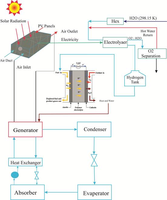
Figure 1. Schematic of the hybrid energy system.
As It is observed, upper surface of solar panel absorbs the sun radiation energy and turns it to both electricity and heat in a PV/T solar panel. Then this electrical energy can be used in electrolysis to split water molecules into hydrogen and oxygen. Hydrogen is then stored in a storage tank for later usage d when the electricity is not available during the night. In this case, a fuel cell is integrated to generate electricity. Furthermore, output hot water of solar panel enters to generator of an absorption chiller. In addition to this energy, heat generated by the fuel cell enters to the generator of absorption chiller to provide higher cooling load. Moreover, power generated by the fuel cell can be used in the domestic consumptions.
3. Thermodynamic Modeling of the Cycle
3.1. Solar Panel Modeling
Photovoltaic / thermal solar panels (PV/T) produce work and heat at a same time and have more efficiency than photovoltaic panels (PV). Joshi et al. are used to modeling of the solar panel.13 Work production of solar panel calculates by following equation:
![]() (1)
(1)
where ηc is solar cell efficiency to producing electricity which 0.38 is considered in this study, βc is packing factor and its value is 0.83 and τg is energy absorption by the glass and its amount is 0.95.13 Usage solar panel thermal energy can be determined by:
![]() (2)
(2)
where hp2z is product of packing factor (glass to glass) with value of 0.1418. Z and hP2Z are calculated by following:13
![]() (3)
(3)
At equation (3), αb and αc are absorption coefficient of black surface with value of 0.9 and absorption coefficient of solar cell with value of 0.85, respectively. At equation (2), UL is total heat transfer coefficient to ambient in front and behind parts of panel which are exposed solar radiations and its value is 4.71 W/m2K.
Output air temperature of the PV/T solar panel can be calculated by following equation base on energy balance:
 (4)
(4)
Which efficiency is given by:
![]() (5)
(5)
Where ![]() is intensity of sun radiation, b is thickness, L is thermal solar panel length and hP2G is penalty factor due to presence of interface between glass and working fluid through absorber plate (glass to glass) which its value is 0.1890.13
is intensity of sun radiation, b is thickness, L is thermal solar panel length and hP2G is penalty factor due to presence of interface between glass and working fluid through absorber plate (glass to glass) which its value is 0.1890.13
3.2. Electrolysis Modeling
In this section, thermodynamic modeling of electro chemical process is presented. Electrolyze energy demand is given by:
![]() (6)
(6)
where ![]() is Gibbs free energy and
is Gibbs free energy and ![]() is thermal energy. The use of the catalyst reduces the activation energy of the reaction. The amount of hydrogen produced by electrolysis is calculated from the following equation:
is thermal energy. The use of the catalyst reduces the activation energy of the reaction. The amount of hydrogen produced by electrolysis is calculated from the following equation:
![]() (7)
(7)
where current density is the current per unit area of the surface (J) and Faraday constant is (F). Input electrical energy to electrolysis can be expressed as:
![]() (8)
(8)
And voltage is given by:
![]() (9)
(9)
V0 is the reversible ideal voltage, anode activation overvoltage is Vact,a, cathode activation overvoltage is Vact,c and electrolyte resistance is Vohm. V0 can be calculated by Nernest equation which is given by:
![]() (10)
(10)
The ohmic overvoltage occurs due to the membrane resistance during the passage of Hydrogen ions. This parameter can be obtained based on Ohm's Law as follow:
![]() (11)
(11)
which in equation (11) is:
![]() (12)
(12)
![]() (13)
(13)
![]() (14)
(14)
In the above equations, ![]() is ion-conducting polymer membrane,
is ion-conducting polymer membrane, ![]() is moisture percent and
is moisture percent and ![]() is ohmic resistante. Overvoltage of anode and cathode are determined by:
is ohmic resistante. Overvoltage of anode and cathode are determined by:
![]() (15)
(15)
![]() (16)
(16)
![]() is the exchange current density which is considered as one of the important factors in the activation overvoltage.
is the exchange current density which is considered as one of the important factors in the activation overvoltage. ![]() is pre-exponential factor and
is pre-exponential factor and ![]() is the activation energy required for the anode and cathode.
is the activation energy required for the anode and cathode.
4. Fuel Cell Modeling
The following assumptions are made to simplify the modeling of the fuel cell:
• The system is in working based on steady stat condition.
• Air consists of 21% Oxygen and 79% nitrogen.
• Operating temperature of fuel cell is constant and output temperature is same as it.
Hydrogen and oxygen operate as the reaction in a fuel cell and electricity DC, water and heat can be generate. The performing reactions in the anode and cathode can be expressed as follows:
|
| (17) |
|
| |
|
|
Reversible voltage of the fuel cell calculated by Nernst equation which is given by:
![]() (18)
(18)
Where ![]() is the temperature of fuel cell,
is the temperature of fuel cell, ![]() is the partial pressure of the reactant j. Partial pressure values are obtained from the following equation:
is the partial pressure of the reactant j. Partial pressure values are obtained from the following equation:
![]() (19)
(19)
![]() (20)
(20)
![]() and
and ![]() are partial pressure of anode and cathode, respectively.
are partial pressure of anode and cathode, respectively. ![]() and
and ![]() are the molar percent of Hydrogen and oxygen, respectively.
are the molar percent of Hydrogen and oxygen, respectively.
![]() (21)
(21)
![]() (22)
(22)
![]() is the water molar percent in anode and cathode.
is the water molar percent in anode and cathode. ![]() and
and ![]() are molar percent of dry gas in anode and cathode, respectively.
are molar percent of dry gas in anode and cathode, respectively. ![]() is ratio of anode Stoichiometry and
is ratio of anode Stoichiometry and ![]() is cathode stoichiometry.
is cathode stoichiometry.
![]() (23)
(23)
![]() (24)
(24)
Saturated pressure is determined by following equation:
![]() (25)
(25)
The voltage is lower than the value of its reversible due to the irreversibility which occurs in the fuel cell. These losses are including activation losses, Ohmic losses and concentration losses which are determined in this study. Therefore, the amount of the fuel cell voltage is as follows:
![]() (26)
(26)
At the start of reaction, activation losses occur due to consumption of some energy for activation of reactants and chemical reaction. This calculates as follows:
![]() (27)
(27)
where α is the displacement coefficient, n is the number of electrodes and R is the universal gas constant. Ohmic losses occur due to loss of electrical resistance. This resistance includes the membrane resistance, electrical, ion resistance in the electrodes and the resistance of the connecting terminals. The Ohmic losses calculate as follows:
![]() (28)
(28)
In the above equation, polymer fuel cell resistance is calculated same as polymer electrolysis cell from Formulas (14-16). Losses of concentration exist in the fuel cell due to changes in the concentration of reactants or products in the area of the electrodes which are calculated as follows:
![]() (29)
(29)
where JL is the limiting current density.
5. Absorption Chiller Modeling
In this section, thermodynamic analyses of a single effect absorption chiller are performed.
A control volume is considered for each component of the chiller which involves inlet and outlet of mass flow, heat and work interactions. In absorption refrigeration system, the mass conservation law including mass balance for the all masses. Several simplifying Assumptions are made in order to render the results more traceable of absorption chiller Modeling is as follows:
• The refrigerant water is stable.
• There is a pressure drop in the expansion valve.14
• Point 13 is in the saturated vapor state.
• The flow in the expansion valve is adiabatic.
• The pump is isentropic.
The coefficient of performance (COP) of absorption refrigeration system is defined as ratio of the evaporator heat load to the generator heat load:
![]() (30)
(30)
The amount of the work done of pumps and heat load of absorbers, evaporators and generators are generally calculated from the following formulas:
![]() (31)
(31)
![]() (32)
(32)
It should be noting that the enthalpy and entropy of the absorption cycle is determined based on the results presented by Yuan and Herold.15
6. Exergy Analysis of Cycle
Exergy is the maximum work obtainable from a process, which can be reached from the balance between the system and environment. Unlike energy, exergy is not conserved and it is destroyed. Generally, exergy is divided into four major parts namely, physical, chemical, potential and kinetic. The last two terms are ineligible as the variation in velocity and elevation is not considerable.
The purpose of this part of the calculation is to obtain the losses of all components of the cycle and then calculating a total loss of the cycle to obtain a better view of the cycle. Additionally, the exergy efficiency of the total of the cycle is defined as follows:
![]() (33)
(33)
![]() (34)
(34)
![]() (35)
(35)
![]() (36)
(36)
![]() (37)
(37)
where ![]() is exergy of heat per unit time,
is exergy of heat per unit time, ![]() is exergy of work per unit time,
is exergy of work per unit time, ![]() is losses of exergy,
is losses of exergy, ![]() is physical exergy,
is physical exergy, ![]() is chemical exergy,
is chemical exergy, ![]() is efficiency of second law of thermodynamics,
is efficiency of second law of thermodynamics, ![]() is exergy by heat of fuel cells and
is exergy by heat of fuel cells and ![]() is cooling exergy of absorption chiller. Moreover, exergy input by solar radiation is calculated as follows:
is cooling exergy of absorption chiller. Moreover, exergy input by solar radiation is calculated as follows:
![]() (38)
(38)
In above equation, ![]() and
and ![]() are solar panel efficiency and temperature of the sun which equal to 84% and 5486.85
are solar panel efficiency and temperature of the sun which equal to 84% and 5486.85 ![]() respectively.
respectively.
More information about parameters of the equation (33) can be obtained in references 16-19. List of exergy losses for various components of the cycle is shown in table 1.
Table 1. Exergy destruction rate for various components of the cycle
| Components of cycle | losses |
| Solar panel |
|
| PEM electrolysis |
|
| PEM fuel cell |
|
| Generator |
|
| Condenser |
|
| Expansion valve |
|
| Evaporator |
|
| Absorber |
|
| Pump |
|
| Heat exchanger |
|
7. Optimization of the Hybrid System
In general, the optimization formulation can be state as follows:
Minimize
![]()
Subjected to
![]() (39)
(39)
![]()
![]()
where x represents the design variable vector and n is the number of design variables. ![]() is the objective function which depends on the values of the design variables.
is the objective function which depends on the values of the design variables. ![]() denotes the inequality constraint.
denotes the inequality constraint. ![]() and
and ![]() are the lower and upper limits of the design variables, respectively and they simply limit the region of search for the optimization. m is number of objective functions u is the number of inequality constraints and s is the number of equality constraints. Also n is the number of the design variables.
are the lower and upper limits of the design variables, respectively and they simply limit the region of search for the optimization. m is number of objective functions u is the number of inequality constraints and s is the number of equality constraints. Also n is the number of the design variables.
Objective Functions
In this study the exergy efficiency and the total cost rate for the objective function were used in an optimization problem based on the Genetic algorithm. This is a multi-objective optimization problem that should be solved simultaneously to determine the best design parameters to maximize the exergy efficiency and minimize the total cost rate. Also, PV/T Length (m), PV/T Width (m), PV/T Mass flow rate (kg/s), Evaporator temperature (0C), Fuel cell temperature (0C) and Electrolysis area (cm2) are considered as design variables which are shown in Table 2.
Table 2. Design variables of the problem.
| Parameters | Design variables | LB | UB | Unite |
|
| PV/T Length | 0.8 | 2.5 | m |
|
| PV/T Width | 0.4 | 0.7 | m |
|
| PV/T Mass flow rate | 0.1 | 2 | kg/s |
|
| Evaporator temperature | 3 | 7 | 0C |
|
| Fuel cell temperature | 75 | 90 | 0C |
|
| Electrolysis area | 200 | 300 | cm2 |
8. Results and Discussion
8.1. The Results of Thermodynamic Modeling and Exergy Analysis
In this section the results of the hybrid cycle modeling including a solar panel, polymer electrolysis, polymer fuel cell and a single effect Li-Br absorption chiller is presented. Our case study is Tehran. Therefore, the intensity of solar radiation of Tehran is considered and all calculations are based on data taken of this city. The annual air temperatures variation of solar panel in Tehran is shown in Figure 2.
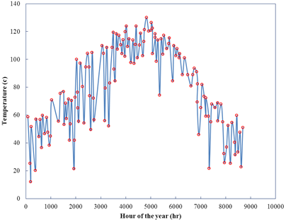
Figure 2. Annual outlet air temperatures of the solar panel per hour.
The power generated by the solar panel is shown in Figure 3. This power enters to electrolysis for producing hydrogen.
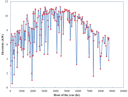
Figure 3. Electricity production by solar panel per hour in a year.
Figure 4 shows the hydrogen production by solar panels. As previously mentioned, this energy is provided by solar panels.
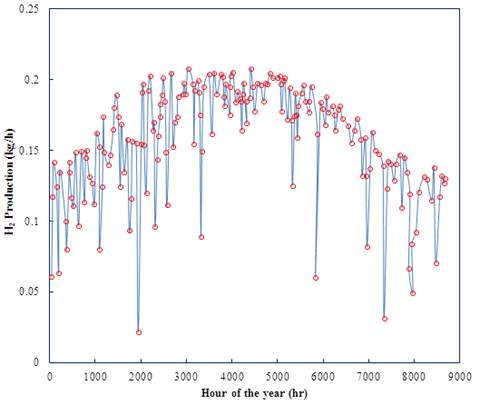
Figure 4. H2 production by solar panel per hour in a year.
Voltage variation per current density in electrolysis is shown in Figure 5. Some over voltages such as the anode and cathode activation overvoltage and the Ohmic voltage causes the voltage of electrolysis to be different from the ideal case. To verify results of the modeling, they are compared with reference.11 Low error is found between experimental data and the code.
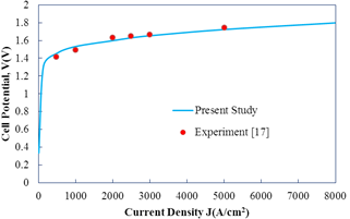
Figure 5. Voltage variation per current density in electrolysis.
Figure 6 shows the polarization curve and the power production of fuel cell. The voltage drop of activation, ohmic and concentration cause a difference between the ideal voltage and the curve. At the beginning of the reaction, some energy use to active the reactants and Chemical reaction. Therefore, the drop of activation is occurred at the beginning of the curve. The effect of this loss is higher in the lower current density. Other drop is the ohmic drop which is caused by resistance against the motion of electrons and ions. According to the ohm's law, resistance against the motion of electrons and ions increase as the current density increases. This drop has almost linear behavior and its value increase with the increasing the current density. This drop is occurred in the middle part of the curve. Drop in concentration due to limitation on the transfer of reactants. Catalyst and gas diffusion layers are layer's porous and when the reactants crossing the porous layers, a drop in pressure and velocity is occurred. By increasing the density, the intensity of the reaction in the catalyst layer increases.
This enhancement results in an increase in the consumption of the reactants, thus, they should be lead rapidly than the catalyst layer. However, transfer rate of reactants have some constraints due to the porous layer. This drop is obtained in the high density. In addition, power generation increases with increasing flow rate but with the excessive rising, this parameter decrease due to the most reduction of current density. The point operation should be choosing before the maximum point of power curve.20
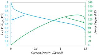
Figure 6. Voltage and power variation per current density in the fuel cell.
Efficiency of fuel cell variation per current density is shown in Figure 7. Efficiency increase with an increase in current density to a value and then decreases. The efficiency of fuel cell is the ratio of power production to heat.
At the beginning, the value of work production is higher than heat with increasing current density. However, the amount of heat is produced gradually more than work and efficiency is decreased.
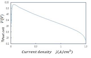
Figure 7. Efficiency of fuel cell variation per current density.
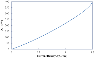
Figure 8. Heat production variation per current density in fuel cell.
Heat production variation per current density in fuel cell is shown in Figure 8. The value of reactants is increased based on increasing the current density and more reactions can be doing in a given time. As a result, the released energy from this reaction is increased and finally the amount of heat production will be greater.
The amounts of work and heat production by the fuel cell are shown in figures 9 and 10, respectively.
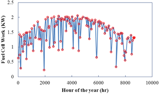
Figure 9. Annual power production per hour by fuel cell.
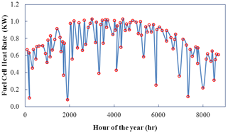
Figure 10. Annual heat production per hour by fuel cell.
8.2. Optimization results
A multi-objective evolutionary based algorithm using NSGA-II is carried out and the results are presented in Figure11 on a Pareto Frontier in the space for the total cost and the exergy efficiency.
Three point A, B and C are shown in Figure 11. At point A the total cost rate and the exergy efficiency are minimum, while at point C the total cost rate and the exergy efficiency are maximum. So the total cost and the exergy efficiency are optimized in point A and C, respectively. For reaching the aim of the multi-objective optimization, the total cost rate must be minimized and the exergy efficiency must be maximized. Since this optimal point do not exist in the result set, point B which is the nearest point to optimal point is considered as optimal point. Value of the design variables and objective functions are presented in Table 3
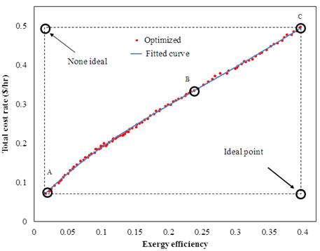
Figure 11. Pareto optimal Frontier in the objectives space for Generation=50 (total cost and exergy efficiency).
Table 3. Optimum value of design variables and objective functions.
| Notation | A | B | C |
| PV/T Length (m) | 0.8532 | 2.4826 | 0.5790 |
| PV/T Width (m) | 0.4214 | 0.5932 | 0.5057 |
| PV/T Mass flow rate (kg/s) | 1.8793 | 1.97 | 1.6153 |
| Evaporator temperature (oC) | 6.3952 | 3.7417 | 3.8705 |
| Fuel cell temperature (oC) | 84.0771 | 80.4615 | 89.9936 |
| Electrolysis area (cm2) | 276.2724 | 202.0043 | 230.8672 |
|
| 0.2 | 0.271 | 0.3932 |
|
| 0.2223 | 0.4149 | 0.4972 |
Exergy destruction rate in various components of the cycle are shown in Figure 12. These are calculated for average values of temperature, heat and work. The exergy destruction rate for solar panel PV/T is higher than other components due to the exergy input from the sun is very high because of the high temperatures.
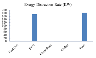
Figure 12. Exergy losses in various components of cycle.
9. Conclusion
In this paper a comprehensive thermodynamic modeling of a hybrid renewable energy system along with an optimization was studied and assessed. The effects of main design parameters of a hybrid system including a PV/T solar panel, PEM electrolysis, a polymer (PEM) fuel cell and one effect absorption chiller of water and lithium bromide are evaluated and their diagrams are obtained. Then the thermo-economic performance of this system is improved using multi-objective optimization algorithm (GA).
According to the exergy analysis for solar panel, the exergy destruction is high due to more exergy input to the solar panel from the sun. Furthermore, the optimum values of the design variables, PV/T Length (m), PV/T Width (m), PV/T Mass flow rate (kg/s), Evaporator temperature (oC), Fuel cell temperature (oC) and Electrolysis area (cm2), are obtained 2.4828, 0.5932, 1.97, 3.7417, 80.4615 and 202.0043, respectively.
Nomenclature
| A | Area, m2 |
| Cp | Specific heat at constant pressure, J/kg ºC |
| ex | Specific exergy, kJ/kJ |
|
| Exergy flow rate, kW |
| G | Solar radiation intensity, W/m2 |
| g | Inquality onstraint |
| h | Specific enthalpy, kJ/kg |
| hp2z | product of packing factor |
| hP2G | Penalty factor |
| I | Current, A |
|
| Intensity of sun radiation, kW/m2 |
|
| Current density per unit area of surface, A/cm2 |
|
| Mass flow rate, kg/s |
|
| Heat rate, kW |
|
| Ohmic resistance, Ω |
|
| Specific entropy, kJ/kg.K |
|
| Temperature, ℃ |
|
| Time, Sec. |
|
| Total heat transfer coefficient |
|
| Velocity, m/s; Voltage, V |
|
| Work rate, kW |
|
| Concentration. % |
|
| energy absorption by the glass |
References
- Barbir F. PEM fuel cells: theory and practice. Elsevier Science & Technology Books. 2005.
- Larminie J and Dicks A. Fuel cell systems explained. 2nd ed. John Wiley & Sons Ltd. 2003.
- Kaushik S.C, Ranjan K R and Panwar, N. L. Optimum exergy efficiency of single-effect ideal passive solar stills. Energy Efficiency, 2013; 6(3):595-606.
- Ay, M., Midilli, A., Dincer, I., Exergetic performance analysis of a PEM fuel Cell. Int J Energy Res, 2006; 30(5):307-321.
- Barclay F.J. Fundamental thermodynamics of fuel cell, engine, and combined heat and power system efficiencies. Proceedings of the Institution of Mechanical Engineers, Part A: Journal of Power and Energy, 2002; 216(6):407-417.
- Ghosh S and De S. Thermodynamic performance study of an integrated gasification fuel cell combined cycle: An energy analysis. Proceedings of the Institution of Mechanical Engineers, Part A: Journal of Power and Energy, 2003; 217(6):575-581.
- Lawn C.J. Technologies for tomorrow's electric power generation. Proceedings of the Institution of Mechanical Engineers, Part C: Journal of Mechanical Engineering Science December 1, 2009; 223:2717-2742.
- Ahmadi P, Dincer I, Rosen M.A. Performance assessment and optimization of a novel integrated multigeneration system for residential buildings. 2013.Energy and Buildings 67, 568-578.
- Yilanci A, Dincer I and Ozturk H.K. Performance analysis of a PEM fuel cell unit in a solar–hydrogen system, International Journal of Hydrogen Energy. 2008; 33(24):7538-7552.
- Dupeyrat P, Ménézo C and Fortuin S. Study of the thermal and electrical performances of PVT solar hot water system. Energy and Buildings. 2012; 68:751-755.
- Zhao P et al. Parametric analysis of a hybrid power system using organic Rankine cycle to recover waste heat from proton exchange membrane fuel cell. International Journal of Hydrogen Energy. 2011; 37(4):3382-3391.
- Ratlamwala T.A.H, Gadall M.A and Dincer I. Performance assessment of an integrated PV/T and triple effect cooling system for hydrogen and cooling production. International Journal of Hydrogen Energy. 2011; 36(17):11282-11291.
- Joshi, A et al. Performance evaluation of a hybrid photovoltaic thermal (PV/T) (glass-to-glass) system. International Journal of Thermal Sciences, 2009; 48:154-164.
- Ahmadi P, Dincer I, Rosen M.A. Exergy, exergoeconomic and environmental analyses and evolutionary algorithm based multi-objective optimization of combined cycle power plants.Energy 36 (10), 5886-5898.
- Yuan Z and Herold K.E. Thermodynamic Properties of Aqueous Lithium Bromide Using a Multiproperty Free Energy Correlation. HVAC and Research. 2005; 11(3):377-393.
- Ahmadi P, Dincer I and Rosen M.A. Energy and exergy analyses of hydrogen production via solar-boosted ocean thermal energy conversion and PEM electrolysis. International Journal of Hydrogen Energy, 2013; 38(4):1795-1805.
- Rosen M.A, Dincer I. and Kanoglu M. Role of exergy in increasing efficiency and sustainability and reducing environmental impact. Energy Policy, 2008; 36(1):128-37.
- Szargut J, Morris D.R and Steward F.R. Exergy Analysis of Thermal, Chemical, and Metallurgical Processes. 1988, New York: Hemisphere Publishing Corporation.
- Bejan A, Tsatsaronis G and Moran M. Thermal Design and Optimization. New York: Wiley. 1996.
- Ioroi, T et al. Thin film electrocatalyst layer for unitized regenerative polymer electrolyte fuel cells. Journal of Power sources, 2002; 112:583-587.


