
International Journal of Materials Chemistry and Physics, Vol. 1, No. 2, October 2015 Publish Date: Sep. 1, 2015 Pages: 189-197
Woven E-glass Fiber Reinforced Epoxy Composite – Preparation and Tribological Characterization
Mainak Sen, Pujan Sarkar, Nipu Modak, Prasanta Sahoo*
Department of Mechanical Engineering, Jadavpur University, Kolkata, India
Abstract
An experimental investigation has been carried out on woven E-glass fiber reinforced polymer (GFRP) composite prepared through VARTM (vacuum assisted resin transfer moulding) process to study its tribological performance. Friction and wear tests are carried out using block-on-roller arrangement under dry sliding conditions. Tribological characteristics of GFRP composites are measured in two principal directions - parallel (PL) and anti-parallel (NL) orientations. The effects of various experimental test parameters such as applied load, sliding time and sliding speed are studied. The micrographs of the worn surfaces are observed by the help of scanning electron microscope (SEM) to know the wear mechanisms. Friction and wear results are observed to be influenced by all the selected test parameters. Wear and friction showed a tendency to increase with increase in time, load and sliding velocity, but at higher load and sliding velocity the matrix softening results in reversing the trend, by formation of transfer film on the counterface. The laminate orientation greatly influences the coefficient of friction and wear where PL shows larger wear and friction values than NL.
Keywords
GFRP, Composite, Vacuum Moulding, Tribology
Received: August 10, 2015
Accepted: August 23, 2015
Published online: September 2, 2015
@ 2015 The Authors. Published by American Institute of Science. This Open Access article is under the CC BY-NC license. http://creativecommons.org/licenses/by-nc/4.0/
Contents
1. Introduction 2. Experimental Details 2.1. Preparation of Material and Test Specimen 2.2. Test Procedure and Parameters 3. Results and Discussion 3.1. Friction and Wear Behaviour of Composite 3.2. SEM Observation of Worn Surface 3.3. Mechanical Properties of Composites 4. Conclusion Acknowledgements
1. Introduction
In recent years, there have been rapid growth in the developments and applications of glass fiber reinforced thermosetting polymer composites such as polyester and epoxy. This is due to the realization of their potential to combine high performance to cost ratios with rapid clean process ability, chemical resistance and the attractions of their intrinsic recyclables. Fiber reinforced polymer matrix composites are finding ever-increasing usage for numerous industrial applications, such as bearing material, rollers, seals, gears, cams, wheels, clutches, blades and many other applications in aerospace and aviation industries etc. Therefore, the tribological behaviour of these materials need to be studied comprehensively as the knowledge of their tribological behaviour is limited and lacks predictability. Only, limited studies have been conducted on the of friction and wear characteristics of these materials [1-8].
In polymer matrix composites (PMC's), normal load and sliding velocity play dominating effects on the friction and wear characteristics as these are responsible for the selection of pressure (p)-velocity (v) condition. According to Amonton’s law of friction, Coefficient of friction (COF) should be independent of p and v. However, in the case of polymeric materials, its often not the case as examined in [9-14]. Apart from that, the generated surface temperature is another equally important parameter in studying the tribological behaviour of polymer composites [2,4,6,15]. An increase in wear intensity can occur due to thermal softening. It is found that little attention has been paid in this respect. Consequently, estimation of tribological properties based on known composite structures and system parameters is often a difficult task. Thus there is a need for better understanding of how and why different types of reinforcement in composites influence the tribological properties at different conditions. Looking upon the incorporation of secondary structural component many researchers have investigated the effects on tribological behaviour of composites when integrated with functionally graded materials (FGM's) such as soft and hard particle inclusion and the results have shown very escalating effects in improvement in tribological as well as in mechanical front, but the incorporation of the fiber or filler material does not necessitate in improvement of the tribological properties as it shows both positive [2,7,8,9,16] and negative [11,13] results on the tribological properties of the polymer.
Apart from above stated parameters, there is another influencing parameter which has a very critical role to play in effecting the tribo-performance of the composite. It is the orientation of the fiber in the sliding direction. Many researchers have studied the effect of the fiber orientation on these properties. The results show that the effect is still controversial [1,12,13,14]. Therefore, the present study is motivated by the fact that there is insufficient published work pertaining to the sliding wear and friction behaviour of woven E-glass fiber reinforced epoxy composites when sliding against smooth metal surface. It presents an experimental investigation on wear and friction of GFRP composite material sliding against smooth EN8 steel roller. The effect of different operating conditions such as sliding speed (roller speed- 100,150,200 rpm), normal load (50, 75, 100 N), sliding time (60, 120, 180 sec), for different orientations (parallel-PL and anti parallel-NL) is studied using block on roller arrangement in a multi tribo-tester. SEM micrographs of worn surfaces are presented to show some features of wear mechanism involved during sliding.
2. Experimental Details
2.1. Preparation of Material and Test Specimen
The material tested in this study is woven E-glass fiber reinforced epoxy composite. The epoxy resin used is Araldite CY 205 IN with a density of 1.27gm/cm3, glass transition temperature of 108°C, hardener used is HY 951 with density of 0.94gm/cm3 was obtained from Huntsman Ltd., India and acetone GR (CH3COCH3) were mixed in an weight ratio of (10:1:4).The woven E-glass fiber fabric of 300g/m2mass of fibers with weave pattern of 0°/90° is used. The specimen is prepared with the help of vacuum assisted resin transfer moulding, where 12 layers of woven glass fabric are laid on a mould surface which is treated with poly vinyl alcohol (PVA) mould releasing agent and then complete vacuum bagging is placed along with other bagging materials as described in [17-22] and then the infused part is allowed to cure at room temperature for 24 hrs as shown in Figure 1. The infused part so obtained from which specimen for mechanical and tribological test are cut, has a nominal thickness of 3.6 mm.
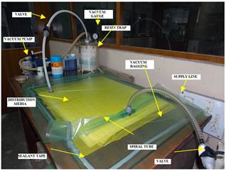
Figure 1. Setup for vacuum assisted resin transfer moulding (VARTM).
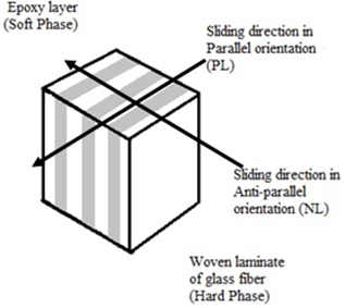
Figure 2. Schematic illustration of the sliding direction on the specimen. (arrow showing sliding direction).
2.2. Test Procedure and Parameters
Evaluation of wear and friction: A Multitribotester TR25 apparatus (DUCOM, INDIA) is used to investigate the friction and wear characteristics of the glass fiber reinforced epoxy composite specimens using block on roller configuration, under dry conditions. During the test the GFRP composite specimens are pressed against a EN8 steel roller. The experiments are conducted with a set of normal load of 50, 75, 100 N and set of sliding velocity at 100, 150, 200 rpm and for sliding time of 60, 120, 180 seconds considering the thermal effect causing degradation of the polymer matrix and corresponding data’s are collected accordingly. The square sized GFRP composite specimens are kept fixed in an attachment in such a way that layered surface is in close contact with the roller the test is conducted at two orientations PL and NL as shown in Figure 2. Speed is assigned only to the roller which is having a diameter of 50 mm.
In the experimental set up the roller is the bottom specimen and at the top GFRP specimen samples are placed with close contact with each other. The frictional force is measured by a frictional force transducer and the wear transducer measures the wear in terms of displacement. The Multi-tribotester TR25 apparatus is shown in Figure 3. The wear morphology of the worn surface of GFRP composite under different orientations are closely examined with the help of scanning electron microscope, JEOL (JSM-6360).
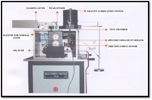
Figure 3. Multi-tribotester TR25 apparatus.
Evaluation of mechanical properties: The tensile test is conducted for the GFRP composite according to ASTM D3039-07 [23] on Instron 8801 where the sample sections are prepared for predicted failure within the gauge length section without fiber pull-out or debonding at the anchorage by providing end tabs for successful introduction of force into the test specimen. Strain controlled test is conducted at a constant strain rate of 1.66×10⁻⁴/sec for determining the tensile strength and to obtain strain-strain data.
3-point bending test is also conducted according to ASTM D790-10 [24] with a constant head- speed of 1.536 mm/min, where the force-displacement and flexural stress-strain data are recorded at the center of the beam. For both the tests, five test specimens are tested under the designed experiment for a statically significant data.
3. Results and Discussion
3.1. Friction and Wear Behaviour of Composite
The results of friction and wear for glass fiber reinforced polymer composites are shown below. Friction and wear behaviour with respect to their different orientations, i.e, parallel (PL) and anti-parallel (NL), are explained under the three influential parameters, i.e, normal load, sliding velocity (roller speed) and time.
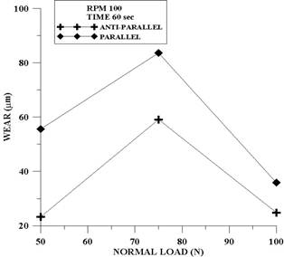
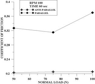
Effect of Normal Load: The results of wear and friction for GFRP composites in two different laminate orientations i.e. parallel and anti-parallel are shown as a function of applied normal load in Figure 4. The results indicate that anti- parallel laminate orientation (NL) shows a better wear resistance in comparison with that of parallel laminate (PL) orientation. It can be observed from the graphs that composite exhibits high initial wear rates and increases with increasing load. This is a typical behaviour seen in most of the polymeric composite materials [5,13].
But beyond 75N, there is considerable fall in wear depth as seen in Figure 4(a). This can be due to the fact that, most of the removed broken, pulled out and fractured glass fibers which are essentially the harder phase in laminated GFRP composites, are caught and remained at the interface and embedded into the softer phase matrix at higher load leading to decrease in wear rate. This process results in covering rubbing surface by glass-epoxy debris, which in turn reduces the measured wear depth.
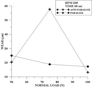
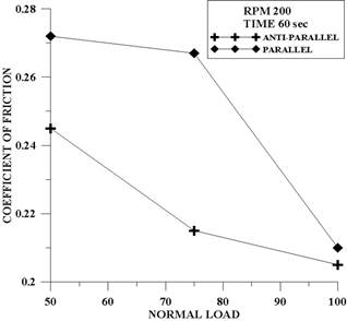
In the friction front, the coefficient of friction(COF) also increases with increase in load at lower speed levels which goes in accordance with the earlier results for epoxy resin based composites[14] and in all the test it is observed that COF levels are less in anti-parallel orientation (NL) than parallel orientation (PL). More over the existence of the glass fiber affects the contact area and junction strength and so contributes directly to higher friction levels as seen in Figure 4(b). At higher range of load and sliding speed, the combined effect leads to increase in the interface temperature which further causes softening of the matrix material resulting in the formation of transfer lubricated film which in turn reduces the wear as well as friction as seen in Figure 5.
(a)
(b)
Figure 4. Wear and friction vs. normal load at roller speed 100rpm and sliding time 60sec.
(a)
(b)
Figure 5. Wear and friction vs. normal load at roller speed 200rpm and sliding time 60sec.
Effect of Sliding Velocity: An increase in sliding velocity generates an additional mechanism to be accounted in wear and friction to those already acting during the wear process. With increase in sliding velocity, temperature rise in the sliding interface occurs and this causes thermal penetration as a result of softening of matrix resin. Consequently the coefficient of friction decreases with the increase in roller speed (sliding velocity), as seen in Figure 6. Similar observation is reported earlier in [1]. The value of friction coefficient at all ranges of sliding velocity is observed to be lower in case of anti-parallel orientation than that of parallel orientation.
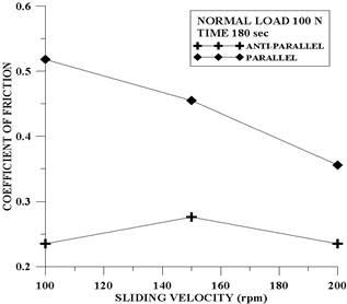
Figure 6. Friction vs. sliding velocity(roller speed) at normal load 100N and sliding time 180 sec.
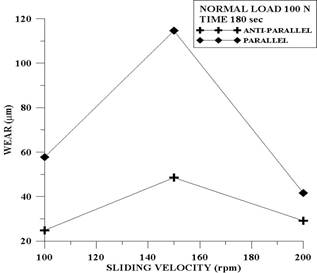
Figure 7. Wear vs. sliding velocity at normal load 100N and sliding time 180sec.
Wear increases with sliding velocity till 150 rpm, then the thermal effect due to high load and sliding velocity become dominant resulting in the softening of matrix material, causing formation of transfer lubricated film on the steel roller which results in decrease in wear rate, as seen in Figure 7.
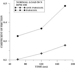
Effect of Time: When the GFRP composite is made to slide against EN8 steel roller, the coefficient of friction is observed to increase gradually with the sliding time. This trend is observed at all ranges of load and sliding velocity, and in both parallel (PL) and anti-parallel (NL) orientation as shown in Figure 8(a). This can be explained by the mechanism that with the wear phenomenon under process, more and more glass particles are generated with the combined effect of load and sliding velocity, thus the existence of the glass fiber affects the contact area and junction strength and so contributes directly to the higher level of friction coefficient and wear, which goes in correspondence with behaviour observed by Tayeb et al. [1,5].
(a)
(b)
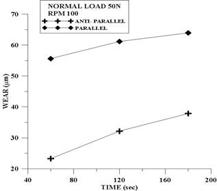
Figure 8. Friction and wear vs. sliding time at normal load 50 N and roller speed 100 rpm.
Wear shows a similar trend of increase consistently with time as illustrated in Figure 8 (b) at all level of loads. When sliding takes place in parallel (PL) orientation, higher values of wear and friction are observed in comparison to that of anti-parallel (NL) orientation. This is attributed to removal of the bulk material when subjected to sliding force. Besides this, the wear debris and fiber fragments can be removed away freely in the parallel (PL) orientation, where as in the anti-parallel orientation (NL) some debris and fiber fragments are caught and trapped in the interface, which goes in accordance with the previous investigation by El-Tayeb et al.[14]. It can be observed that wear and friction in case of parallel (PL) orientation are higher in magnitude than that for anti-parallel (NL) orientation. The comparison of friction and wear for parallel and anti-parallel laminate orientations, as evident from the above graphs can be explained with the help of proposed wear mechanism discussed by Tayeb et al. [5].The glass fiber provides better wear resistance than that posed by the matrix material i.e. epoxy. During sliding in NL orientation, most of the removed, broken, pulled out and fractured glass fibers from the relatively harder phase, remain at the interface and get embedded into the softer matrix phase i.e. epoxy. These results in covering the rubbing surface by glass fragments, which in turn reduce the amount of removed bulk material and the measured value of wear depth (µm). Moreover, when the harder phase covers the sliding surface, then the rubbing process will be dominant which would invariably increase the friction coefficient with time. This is supported with the micrograph of the surface shown later, in which the broken fiber pieces are moved in the direction of sliding towards the softer phase. Furthermore, the fiber ends are seen to be cut or fractured by the counterface and exposed to sliding on their length and produce smaller particles from the fractured fibers. On the other hand, the proposed wear mechanism for parallel (PL) orientation, suggests that most of the wear debris from both the glass fabric and epoxy are moved out freely from the interface which results in increase in the measured wear depth.
3.2. SEM Observation of Worn Surface
Typical wear mechanisms of polymer matrix composites are fiber breaking, fiber-matrix debonding and matrix fracture [1,5,7,9,11,13,14]. Other important mechanisms are fiber pull out, matrix wear related to fiber movement, pealing of the matrix, shear deformation of the fibers. Different mechanisms observed are discussed in relation to the laminate orientation parallel (PL) or anti-parallel (NL) and are supported by SEM micrographs. Figure 9 shows the SEM micrographs of the sample surface before test.
Fiber Breaking: The fibers used in this investigation are glass fiber. These fibers are brittle in nature and are well known for brittle fracture. Due to the applied loads and depending on the fiber orientation with respect to the sliding surface, two types of fracture can be noticed as shown in Figure 10 and Figure 11.In the case of perpendicular orientation of the fiber i.e. in anti-parallel laminate (NL), initial fracture of the fiber might be due to bending of the fiber caused by the transverse load acting due to direction of rotation of the steel roller. If the orientation of the fibers is parallel to the direction of the rotation of the roller that would led to high stresses causing shear failure of the fiber.
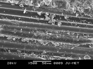
Figure 9. Fiber orientation normal to sliding direction before test.
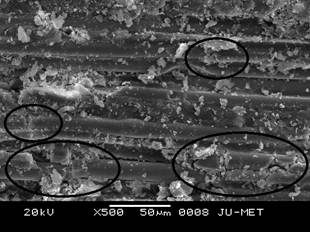
Figure 10. Fiber orientation normal to sliding direction after test.
Fiber-Matrix Debonding: This mechanism consists of two parts, first of all the fiber-matrix debonding where the material is removed near the fibersas seen in Figure 12. The other is where matrix material above an underlying fiber is removed, exposing the fiber as seen in Figure 13. The fiber matrix debonding is dependent on the fiber orientation with respect to the sliding direction. In the parallel case this is due to the behaviour of the fiber, where due to applied load the fiber moves aside. Whereas, in the perpendicular orientation, this may be due to bending of fibers.
Matrix Fracture: Matrix fracture is a mechanism where, due to applied normal load stress exists in the matrix material and this yields the formation of large cracks. To give a clear separation of this mechanism with fiber-matrix debonding, these cracks are only taken as a result of applied stress as long as there is no direct relation with fibers. Figure 14 shows such crack in the matrix. It can be said that this crack is strongly related to the effect of fiber orientation parallel or anti-parallel and might be the result of start of fiber-matrix debonding.
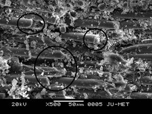
Figure 11. Fiber orientation parallel to sliding direction after test.

Figure 12. Wear track, fiber orientation parallel to sliding direction.
Shear deformation of fibers: In the case of parallel fiber orientation, fibers are subjected to shear forces when the roller surface slides over these. When this force becomes too high, it is when most of the matrix material has already been removed and the entire load is carried out by the fibers, they will break. Not a clear break and removal of the fiber, but shear and brittle fracture, resulting in lots of small glass fiber fragments is seen in Figure 15.
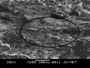
Figure 13. Wear track, fiber orientation perpendicular to sliding direction.
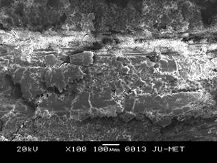
Figure 14. Micrograph presenting matrix fracture in wear track.
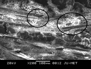
Figure 15. Glass fiber fragments generated by shear deformation of fiber.
3.3. Mechanical Properties of Composites
Table 1. Dimension of GFRP composite coupons for tensile test
(G.L= gauge length, W= width, T= thickness).
| Specimen Type | Number of Coupons | Total Length(mm) | Dimension (mm) | ||
| G.L | W | T | |||
| Rectangular 00/900 | 5 | 300 | 250 | 25 | 3.6 |
Table 2. Effective material properties of GFRP laminate composite in tension.
| Specimen No. | Tensile Strength (MPa) | Average | Standard Deviation |
| Specimen-1 | 187.42 | 192.54 | 5.584 |
| Specimen-2 | 185.2 | ||
| Specimen-3 | 199.06 | ||
| Specimen-4 | 192.72 | ||
| Specimen-5 | 198.31 |
Table 3. Dimension of GFRP composite coupons for flexural test.
| Specimen Type | Number of Coupons | Total Length (mm) | Dimension (mm) | |
| Width | Thickness | |||
| Rectangular 00/900 | 5 | 69.12 | 14.4 | 3.6 |
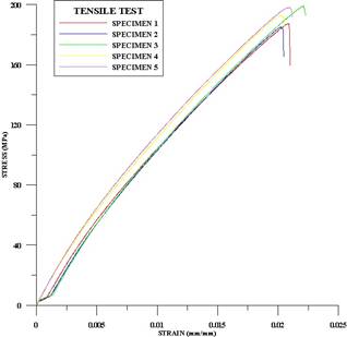
Figure 16. Tensile stress-strain relationship of 00/900 woven laminated composite.
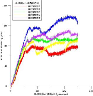
Figure 17. Flexural stress-strain relationship of 00/900 woven laminated composite.
Table 4. Effective material properties of GFRP laminate composite in three-point bending test.
| Specimen No. | Flexural Strength (MPa) | Average | Standard Deviation |
| Specimen-1 | 82.51 | 103.892 | 19.27 |
| Specimen-2 | 139 | ||
| Specimen-3 | 98.29 | ||
| Specimen-4 | 92.66 | ||
| Specimen-5 | 107 |
Tensile test: Table 1 shows the dimension of GFRP composite coupons for tensile test. The results obtained from the test are plotted and the graphs obtained are in correspondence with the standard characteristics shown by the thermosetting polymer based composites. There is only one stage in the stress-strain curve, as both fiber and matrix showed elastic behaviour, as the thermosetting polymer does not show appreciable plastic deformation. In general all tested coupon shows a linear stress-strain relationship up to failure as represented in Figure 16. Table 2 list the average value and standard deviation of the tensile strength from the result of tensile test. The tensile strength is calculated from the maximum tensile load and the average width and thickness obtained from three different places in the gauge section. Maximum tensile stress ranges from 185.2 to 199.06 MPa with the strain value ranging from 0.2047 to 0.2228 mm/mm.
Three-point bending: Table 3 shows the dimension of GFRP composite coupons for flexural test.The results obtained from the test are then plotted and the graph was obtained, Figure 17. Table 4, list the average value and standard deviation of the flexural strength from the result of three point bending test. Maximum flexural stress ranges from 82.51 to 139 MPa.
4. Conclusion
Based on friction and wear results of GFRP composite, following conclusions can be drawn:
• The wear rate of GFRP composite strongly depends on the experimental test parameters i.e. normal load, sliding speed and sliding time.
• Wear and friction show a tendency to increase with time, load and sliding speed. But at higher load and sliding velocity levels the matrix softening occurs resulting in reversing the trend. Formation of transfer lubricating film on the counter surface results in reduced friction and wear.
• Friction and wear properties of glass fiber reinforced composite are greatly influenced by laminate orientations with respect to sliding direction. The wear and friction coefficients of GFRP composite in parallel orientation (PL) are substantially and consistently larger than anti-parallel orientation (NL) This is due to continuous exposure of fresh fiber to the counterpart.
• The combined effect of load and speed causes an increase in temperature at the interface between EN8 steel roller and the composite, which results in the matrix softening and formation of transfer lubricated film. Therefore, interface temperature plays a significant role in determining the wear rate and friction coefficient.
• Although the sliding wear tests are conducted against smooth EN8 steel roller surface, various wear mechanisms are observed. These mechanisms are matrix cracking, fiber breaking, fiber matrix debonding and fragmentation.
Acknowledgements
This paper is a revised and expanded version of a paper titled "Characterization of tribological properties of woven E-glass fiber reinforced epoxy composite" presented at International Conference on Smart Technologies for Mechanical Engineering, 25-26 Oct, 2013, Delhi, India
References
- N.S.M. El-Tayeb, and I.M. Mostafa, Wear, 1996, vol195, pp 186-191.
- V.K. Srivastava,and J.P.Pathak, Wear, 1996,vol 197,pp 145-150.
- H.Unal, U.Sen, and A.Mimaroglu, Tribology International, 2004, vol 37, pp 727-732.
- N.S.M. El-Tayeb,B.F. Yousif and P.V. Brevern, American Journal of Applied Sciences, 2005, vol2-11, pp 1533-1540.
- N.S.M. El-Tayeb, B.F. Yousif, and T.C. Yap, Wear, 2006, vol 261,pp 443-452.
- Thomas O. Larsen,Tom. L. Andersen, Bent Thorning , Andy Horesewell, and Martin E.Vigild, Wear,2007, vol 262 pp1013-1020.
- V.K. Srivastava and S.Wahne, Material Science and Engineering, 2007, volA 458,pp 25-33.
- Siddhartha, A Patnaik, and A D.Bhatt, Materials and Design, 2011, vol 32, pp 615-627.
- N.Mohan, S.Natarajan, and S.P Kumareshbabu, Materials and Design, 2011, vol 32, 1704-1709.
- J.Bijwe, J.Indumathi, J. John Rajesh, and M.Fahim, Wear, 2001, vol 249, pp 715-726.
- HPihtili and NTosun, Composite Science and Technology2002, vol62, pp 367-370.
- J. Quintelier , P. De Baets , P. Samyna, and D. Van Hemelrijck,Wear,2006, vol261, pp 703-714.
- N.S.M.El-Tayeb and B.F. Yousif, Wear, 2007, vol 262, pp1140-1151.
- N.S.M.El-Tayeb,B.F. Yousif, and T.C.Yap, Tribology International, 2008, vol 41, pp 331-340.
- H Pihtili, and NTosun, Wear, 2002, vol252, pp 979-984.
- S S Kim, Min Wook Shin, andHo Jang, Wear, 2012, vol27-275, pp 34-42.
- Vacman's Notes, www.vacmobiles.com.
- B Yenilmez, MSenan, and E.Murat Sozer, Composite Science and Technology, 2009, vol 69, pp 1710-1719.
- J B.Alms, J L. Glancey, and S G. Advani, Composite Structure, 2010,vol92, pp 2811-2816.
- Marsh G. SCRIMP in contest, Reinforced Plastics, 1997, vol. 41(1), pp. 22-26.
- D. Bender, J. Schuster, and D.Heider, Composite Science and Technology, 2006, vol 66, pp 2265-2271.
- H.Gu, Materials and Design, 2000, vol 21, pp 461-464.
- ASTM D3039/D3039M-07, Standard test method for tensile properties of polymer matrix composite materials, American Society for testing and materials.
- ASTM D790-10, Standard test methods for flexural properties of unreinforced and reinforced plastics and electrical insulating materials, American Society for testing and materials.


