
International Journal of Materials Chemistry and Physics, Vol. 1, No. 3, December 2015 Publish Date: Sep. 18, 2015 Pages: 246-252
Managing Mineral-Based Heat Transfer Fluids to Help Maintain a Safe and Effective Heat Transfer Plant
Christopher Ian Wright*
Global Group of Companies, Cold Meece Estate, Cold Meece, Staffordshire, United Kingdom
Abstract
Once a heat transfer fluid (HTF) has been sampled it is chemically analysed according to defined international standards. However, the technique for sampling can vary from organisation to organisation. The impact of sampling technique is explored in the current report as its impact on subsequent test results is not widely acknowledged even though chemical analysis in the laboratory occurs sometime after the HTF has been sampled at the client’s site. Data is presented to show that the closed sampling of mineral-based HTFs is important in gaining a representative HTF as it helps to prevent light-chain hydrocarbons escaping from the sampled HTF. When taking a closed sample from an operating plant, repeated analyses should be conducted on samples and multiple samples should be taken on each visit and this should be repeated regularly throughout the year as part of a HTF condition maintenance programme. The current report highlights the importance of gaining both a representative sample and repeated laboratory analyses in order to maintain a safety and effective plant.
Keywords
Heat Transfer Fluid, Heat Transfer Fluid System, Sampling and Chemical Analysis
Received: August 9, 2015
Accepted: September 5, 2015
Published online: September 17, 2015
@ 2015 The Authors. Published by American Institute of Science. This Open Access article is under the CC BY-NC license. http://creativecommons.org/licenses/by-nc/4.0/
Contents
1. Introduction 2. Experimental Methods 2.1. Sampling Using a Closed Sampling Device ("Best Practice") 2.2. Laboratory Analysis of a Mineral-Based Heat Transfer Fluid ("Condition Based Monitoring") 2.3. Data Analysis 2.4. Analysis 3. Results 3.1. Reliability and Reproducibility of Repeated HTF Samples 3.2. The Importance of Gaining a Representative Sample 4. Discussion 4.1. Overview of Main Findings 4.2. The Importance of Using a Closed HTF Sampling Device 4.3. Avoiding Spurious Laboratory Test Results 4.4. The Impact of the Current Findings in Relation to Plant Safety 5. Conclusions Abbreviations Acknowledgements
1. Introduction
The use of heat transfer fluids (HTF) is growing globally both in terms of value and potential usage. Reports claim that the global HTF market was worth 1.67 million in 2011 and is expected to grow by fifty percent by 2017 [1]. The use of HTFs is growing based on The Australian Institute’s projections for electricity generated from solar power plants [2]. Indeed, estimates suggest that electricity output is growing at forty percent per year and by 2020 this technology will provide 20 GW of electricity globally [2] and contribute 25% of energy requirements by 2050 [3].
Industrial plants use HTF as a heat carrier. A HTF is heated and circulates through a closed system and ends with an object being heated indirectly [4]. The process of heat transfer refers to the transfer of heat from a higher temperature object to a relatively lower temperature object and the object being heated is maintained so that thermal stability is reached [5]. Table 1 outlines some of processes where heat is used in the chemical, plastics and solar industries. This is not, however, an exhaustive list as HTFs are used in other industries including bitumen and tar; mineral oil; rubber; food; soaps and detergents; wood and paper; construction materials, stones and earths; textile; metals; electrical; shipping; aircraft and airlines; heating heat supplies; and, energy generation [5]. Likewise, not all HTFs have the same chemistry. Types of HTFs include, for example, mineral-based HTFs, highly refined mineral HTFs, silicone, aromatics and polyalkylene glycols (please see [5] for a range of HTFs used in industry). Synthetic HTFs, containing eutectic mixtures of biphenyl and diphenyl oxide [5], are commonly used in commercial solar plants [6].
Table 1. Industries and processes where heat transfer fluids (HTF) are used.
| Industry | Industrial process | Type of HTF used in industry |
| Chemicals, plastics [5] | a. Distillation plants. b. Polymerization plants and cooling of reaction plants. c. Esterification plants. d. Gelatinizing channels. e. Drying plants (drum driers, drying cabinets, drying channels). f. Plants for the concentration of acids and lyes (evaporation plants). g. Evaporators. Calendars for foil production. h. Automatic spraying plants, extruders and presses for plastic semi-products. i. Containers for the dye and varnish industry. j. Synthetic resin plants. k. Plants for processing and transport of viscous substances cannot be pumped at room temperature. l. Heat recovery from flue gases of combustion and reaction processes. | Mineral-based HTF and / or synthetic based HTF |
| Food [5] | a. Large kitchens. b. Pommes-frites plants. c. Potato chips plants. d. Plants for fat hardening and rendering. e. Bottle cleaning plants. f. Can washing plants. g. Spray drying plants for milk powder and blood powder production. h. Roller driers. i. Fat and oil vats. j. Baking ovens. k. Plants for the production of sweets. l. Plants for chocolate production. m. Plants for starch drying. n. Plants for the removal of smelly waste gases. | Highly refined mineral-based HTF |
| Solar, energy source [2] | a. Concentrating solar thermal using the following CSP technologies: b. Solar troughs c. Linear Fresnel d. Dishes e. Towers f. Fresnel lens | Synthetic based HTF |
Routine, regular sampling and chemical analysis (SACA) of a mineral-based HTF is important. Recent research assessed the impact of sampling frequency on the overall condition of mineral-based HTFs and showed increased sampling frequency linearly correlated with improvements in the overall condition of the HTF [7]. However, even when sampled more frequently (more than once per year), the total acid number and closed flash point temperature need to be monitored as these were found to be most frequently out of specification when sampled annually [8].
The objective of any fluid maintenance programme is to assess the condition of a HTF and to avoid any surprises even though it is well-known that a HTF will thermally degrade over time. All laboratory analyses are conducted according to ISO14001 [9] and ISO17025 [10] and tests are globally accepted standards. The results from laboratory tests are used to determine if a HTF is in or out of specification (according to the safety data sheet) and what corrective steps, if out of specification, are required.
As a HTF thermally degrades it forms "light-chain" and "heavy-chain" hydrocarbons. Light-chain hydrocarbons can build-up in a HTF and need to be removed from the HTF system, which can be done using a light-ends removal kit. Heavy-chain hydrocarbons are heavier compounds and detected by the build-up of carbon residue in a HTF [5]. Oxygen plays a further part in the decomposition of HTFs. Indeed, when exposed to atmospheric air, a HTF will oxidise at a far lower temperature than its operating temperature. Furthermore, for every 11 degrees Celsius rise in the temperature of a HTF, the rate of oxidation will double and this works to accelerate the decomposition of a HTF [5]. Light-chain hydrocarbons, heavy-chain hydrocarbons and oxidation state can be assessed in the laboratory from measurements of flash point temperature, carbon residue and total acid number, respectively, of a sampled HTF.
The sampling of a HTF can potentially lead to erroneous laboratory test results, especially in the case that a HTF is exposed to air during sampling and light-ends are allowed to escape. Furthermore, it is also important to be able to sample a HTF whilst in operation (i.e., whilst hot and circulating through the HTF system). The current articles reviews the importance of closed hot sampling as opposed to open closed sampling. Moreover, the reliability and reproducibility of this approach is explored in a small number of sites (n=11) where two samples were taken, thereby allowing the sample results to be compared.
2. Experimental Methods
This section is divided into three key parts:
1. A description of the best-practice methods used to sample HTFs whilst still in operation.
2. The laboratory analysis tests used to assess the condition (specifically thermal cracking, which is the main focus herein) of a HTF.
3. An explanation of how the test results were analysed to assess how reliably and reproducibly HTFs can be sampled.
2.1. Sampling Using a Closed Sampling Device ("Best Practice")
It is imperative to gain a representative sample of a HTF and this is can be done whilst the HTF is in operation and circulating through the HTF system. This technique draws a live sample into a closed sampling device to avoid the HTF coming into contact with air. This is done to make sure that decomposition by-products remain in the HTF and do not escape to the atmosphere. But also to ensure the HTF cools to ambient temperature with the flash point components trapped in the HTF sample. This is done to get an accurate measurement of flash point components in the HTF. Indeed, flash point temperatures of a HTF decline as the composition of flash point components (i.e., light-chain hydrocarbons form as a result of the HTF thermally cracking, which occurs with extended use at high temperature over prolonged periods of time. A HTF sample is taken by extracting a 500 ml sample whilst the HTF is in operation and at operating temperature. This sample is drawn into a closed sampling device to gain a representative sample. This is because it stops the HTF being exposed to air and the escape of light-chain hydrocarbons ("light-ends"). It also avoids thermal burns to the engineer taking the sample. It is important to also mention that the closed sample is taken according to standard operating procedures to ensure the same method is used every time.
2.2. Laboratory Analysis of a Mineral-Based Heat Transfer Fluid ("Condition Based Monitoring")
Once a sample has been collected, it is allowed to cool to room temperature before any chemical analyses are conducted. All laboratory analyses are conducted according to ISO14001 [9] and ISO17025 [10]. The content of light-chain hydrocarbons (flash point temperatures) and heavy-chain hydrocarbons (carbon residue) are routinely analysed to assess the extent of thermal cracking.
Global Heat Transfer (please see www.globalheattransfer.co.uk) routinely measures 11-specific parameters to gauge the overall condition of a HTF, which includes both mineral and synthetic based HTFs. The specific parameters measured and test methods used are outlined in Table 2.
Table 2. Chemical analyses conducted in the laboratory.
| Parameter | Unit | Test method |
| Carbon residue | % weight | IP14 |
| Closed flash point | °C | ASTM D93 |
| Open flash point | °C | ASTM D92 |
| Fire point | °C | ASTM D92 |
| Strong acid number | mg KOH/g of sample | IP139 |
| Total acid number | mg KOH/ g of sample | IP139 |
| Viscosity | mm2/s at 40°C | IP71 |
| Water content | ppm | ASTM D6304 |
| PQ analyser (X1) | ferrous debris score | PQ Analex Method |
| Particulates (e.g., iron, silicon) | ppm less than 5 µm | ASTM D5185 |
2.2.1. Light-Chain Hydrocarbons
("Light-Ends")
The build-up of light-chain hydrocarbons can be quantified by measuring flash point temperature (Table 2 and 3). The principle being that for a mineral-based HTF, a high flash point temperature reflects a low proportion of light-chain hydrocarbons in a HTF and low flash point temperature reflects a high proportion of light-chain hydrocarbons. Light-chain hydrocarbons ignite when exposed to a naked flame and it is not surprising that the test used to measure flash point temperature identifies the point that the vapours in a HTF ignite when a naked flame is introduced. Flash point temperature is measured in two ways – open and closed. Open flash point temperature simulates the mixing of flammable vapours in air, whereas closed flash point temperature prevents the vapours from mixing with air. The open flash point temperature is higher than the closed flash point temperature because when exposed to air the most volatile escape which increases the open flash point temperature and decreases the composition of light-chain hydrocarbons in the HTF (Table 3). In day-to-day practice, it is imperative that the closed flash point temperature of a HTF is maintained above 100 degrees Celsius.
The objective of a routine maintenance programme is to monitor the condition of the HTF and, with respect to closed flash point temperature, ensure it remains above 100 degrees Celsius, Global Heat Transfer normally advise that a mineral-based HTF, such as GlobalthermTM M (please see http://www.globalheattransfer.co.uk/heat-transfer-fluids/high-temperature-thermal-fluid/globaltherm), is monitored every 3 months as research has shown that the overall condition of a HTF is better when sampled more frequently [7].
2.2.2. Heavy-Chain Hydrocarbons
("Heavy-Ends")
Carbon can lead to system fouling as carbon builds-up on the internal surfaces of the thermal system. At levels below 1%, carbon remains soft and can be removed using a suitable thermal system flushing fluid, such as GlobalthermTM C1. At levels above 1%, however, carbon begins to bake onto the internal surfaces of pipes and heating coils and can no longer be removed so easily. When carbon residue reaches these levels the HTF will need to be replaced and the HTF system cleaned and flushed to try and remove carbon that has baked onto the internal surfaces of the HTF system.
Table 3. What the chemical testing says about the condition of a mineral-based heat transfer fluid.
| Parameter | What insight is provided by this chemical test? |
| Carbon residue | Composition of heavy-chain hydrocarbons |
| Closed flash point | Composition of light-chain hydrocarbons |
| Open flash point | Composition of light-chain hydrocarbons |
The extent of heavy-chain hydrocarbons in a sampled HTF is determined by measuring the carbon residue in a HTF and this is expressed as a percentage of the overall volume of the HTF sample.
Table 4. The reliability and reproducibility of carbon residue and flash point temperatures for a mineral-based heat transfer fluid (HTF).
| ANOVA single factor | |||||
| Mean | Reliability (within groups variance) | Reliability (between groups variance) | P-value | Reproducibility (CV, %) | |
| Carbon residue (percentage weight) | 0.195 | 0.006 | 0.049 | 0.001 | 40.705 |
| Closed flash point (°C) | 146.318 | 54.227 | 2953.427 | <0.0001 | 4.703 |
| Open flash point (°C) | 202.591 | 71.864 | 208.682 | 0.047 | 3.393 |
Results are taken from 11 HTF systems. Abbreviation: CV, coefficient of variation. This was calculated as ((√within-groups variance)/mean) x 100.
2.3. Data Analysis
Data is presented as means, variances and were calculated using Microsoft Excel 2007. A P-value <0.05 indicated that statistical significance had been reached. Analysis was conducted as follows.
2.4. Analysis
Retrospective laboratory test reports were searched to identify test facilities where HTF samples were taken twice. These samples were tested for reliability and reproducibility.
2.4.1. Reliability
This was assessed by calculating the within and between group variance assessed using a single factor analysis of variance (ANOVA) [11]
2.4.2. Reproducibility
This was assessed using the coefficient of variation (CV) and calculated using this equation: ((√within-groups variance) /mean) x 100 [11].
3. Results
This section is divided into two parts. The first outlines the reliability and reproducibility of taking HTF samples. The second discusses the importance of gaining a representative sample in terms of the accurately predicting the safety of the overall HTF system.
3.1. Reliability and Reproducibility of Repeated HTF Samples
Table 4 presents the reliability and reproducibility for samples of mineral-based HTF.
3.1.1. Between Group Variance (Reliability)
In all cases the between groups variance was higher than the within group variance which is not surprising as these fluids were not standardised and represent a range of different starting values.
3.1.2. Within Group Variance and Coefficient of Variation (Reliability)
Data shows that the within group variance was considerably lower, on average, for carbon residue than for flash point temperatures.
3.1.3. Coefficient of Variation (Reproducibility)
The reproducibility for flash point temperatures is markedly lower than carbon residue. A further observation is that the coefficient of variation was lower, for open flash point compared with closed flash point temperature. However, both had good reproducibility with values below 5%. Le.
3.2. The Importance of Gaining a Representative Sample
Routine chemical analysis conducted in the laboratory is dependent on gaining a representative sample. Results are defined as false-positive, false-negative, true-positive and true-negative. These four outcomes are discussed in more detail below.
3.2.1. False-Positive Laboratory Test Result
Scenario: The HTF has a high flash temperature, but the laboratory test predicted a low flash temperature.
Description: This scenario would occur when light-chain hydrocarbon levels are low, but the subsequent chemical analysis predicts a flash issue when there is no issue with the HTF as the light-chain hydrocarbons composition is low.
The consequences of this type of error would not be catastrophic to the HTF system, but could lead to the customer being misled or taking inappropriate action to correct the flash point issue.
Potential cause: The exact source of this scenario is not clear. It could be a result of operator error, mixing of samples, or even failure of the laboratory equipment. However, this scenario highlights the importance of taking multiple samples and conducting repeated measurements in the laboratory.
Potential fix: Conduct repeat testing on the sampled HTF.
3.2.2. False-Negative Laboratory Test Result
Scenario: The HTF has a low flash temperature, but the laboratory test predicts a high flash temperature.
Description: In this scenario the sampled HTF has a high composition of light-end hydrocarbons and, in the case it was sampled to air, the flash point temperature would be higher than it actually is because may be because the most volatile light-chains have escaped from the HTF during sampling [14]. This has been shown in Figure 1 where the closed flash point temperature of a HTF was higher (+58°C) when sampled using an open sampling device.
Potential cause: Sample was taken to atmosphere (see Figure 1).
Potential fix: Sample to a closed device, avoiding exposure to air.
3.2.3. True-Positive Laboratory Test Result
Scenario: HTF has a low flash temperature and the laboratory test predicted a low flash temperature.
Description: When a HTF is collected into a closed sampling device, the light-chain hydrocarbons will be prevented from escaping to atmosphere and remain in the HTF. Meaning that when they are chemically analysed, the high content of light-hydrocarbons would give a low flash temperature and this would be an accurate representation of the HTF system’s closed flash temperature. The difference between sampling approaches (open versus closed) may therefore be a potential source of error with open samples producing potentially erroneous flash temperature predictions and this may have implications to the longer-term safety of the plant.
Potential cause: Not applicable.
Potential fix: Not applicable.
3.2.4. True-Negative Laboratory Test Result
Scenario: The HTF has high flash temperature and the laboratory test predicted a high flash temperature.
Description: Virgin HTFs are expected to have a relatively high flash point temperature. In this scenario the composition of light-chain hydrocarbons would be expected to be low. Sampling to a closed device would seem to have little impact, however, it is important to realise that the status of the HTF is not known at the time of sampling so a closed device is always recommended. Also, even a fluid with a high flash point temperature will have a certain composition of light-chain hydrocarbons and so sampling to a closed device is even more important to ensure the smaller volume of light-chain hydrocarbons remain in solution and can be quantified.
Potential cause: Not applicable.
Potential fix: Not applicable.
4. Discussion
4.1. Overview of Main Findings
Prior to being tested in the laboratory, a mineral-based HTF is sampled and this needs to be conducted so that flash point components remain in solution and a representative sample is gained. This is important as the ‘best practice’ for the sampling of mineral-based HTF samples is to gain a sample whilst the HTF is in normal operation. This means that volatile light-chain hydrocarbons will not be exposed to air, will not vaporise and will mean that the composition of light-chain hydrocarbons will be accurately reflected in the HTF sample that has been obtained. Thus, when sampling a HTF it is preferable to do this using a closed sampling device. A further consideration is the number of samples. Past research has shown that the condition of a HTF improves when it is sampled more frequently. The current article outlines the importance of conducting repeated analyses on the same HTF sample or repeated analyses on multiple HTF samples to reduce the chance of gaining spurious test results.
4.2. The Importance of Using a Closed HTF Sampling Device
Past research documents the importance of regular sampling and chemical analysis [7]. However, this assumes that all HTF samples are taken using the same technique [8]. The current report discusses the potential impact of open and closed sampling techniques on test results. Furthermore, it is also clear that chemical analysis is conducted after sampling and so the process of sampling has a direct impact on the test results obtained. This means that the sampling technique needs to be standardised to ensure a representative sample is obtained every time. This report shows that this is best done using a closed sampling device that prevents the HTF sample coming into contact with air and avoids volatile vapours escaping from the HTF.
4.3. Avoiding Spurious Laboratory Test Results
The current study also assessed reliability and reproducibility based on two repeat samples and this demonstrated that reproducibility was good (i.e., less than 5%), but that reliability was not as consistent. This finding emphasises the need for repeated measurements either on the same sample or on multiple samples of a HTF. The optimal number of samples is unclear and requires further research. The impact of impact of sampling from different sites in the HTF system also needs to be defined. All these aspects need to be controlled and considered in the standardised operating procedure, which should be defined according to the HTF system being sampled and in consultation with the client. This is because some sites may have a small HTF volume and only one sample may be required, whereas other HTF systems may have a much larger HTF volume, and to get a better overall representation it may be more appropriate to take multiple HTF samples from multiple sites on the system.
4.4. The Impact of the Current Findings in Relation to Plant Safety
This is the first report to demonstrate the direct impact that sampling can have on chemical analysis conducted in the laboratory. It is important to realise the safety implications of an inadequate sampling program. Indeed, it is recommended that HTFs are sampled and chemically analysed at least annually if operating near the upper operating temperature of the HTF. This is defined by the HTF manufacturer and also the insurance company [7]. Sampling and chemical analysis is recommended bi-annually if operating twenty degrees Celsius below this level; however, current research suggests the overall condition of a HTF is improved when it is sampled more than once per year and the most optimal condition ratings were obtained when the HTF was sampled every 3 months [7]. The second point is the management of the potential fire risk that a HTF system presents. This could be as a result of the HTF operating above its flash point temperature or the HTF has a low starting flash point temperature. This risk can be assessed by monitoring the flash point temperature and needs to be conducted according to ATEX Directive 99/92/EC (ATEX 137 or ATEX Workplace Directive) and ATEX Directive 94/9/EC (ATEX 95 or ATEX Equipment Directive) in Europe and regulations 7 and 11 of the Dangerous Substances and Explosive Atmospheres Regulations 2002 (DSEAR) in the UK [14].
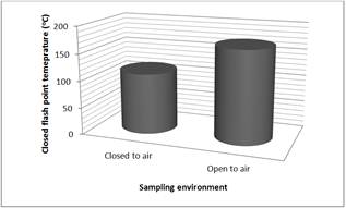
Figure 1. The effect of sampling environment (open or closed to atmosphere) on closed flash point temperature of a mineral-based HTF. Data was extracted from one system.
5. Conclusions
Gaining a representative sample is important in the assessment of a HTFs flash point temperatures and the plants overall safety. A representative sample of the HTF can be gained by using a closed sampling device as this stops the HTF sample coming into contact with air, which can lead to potentially erroneous results (please see Figure 1). The reliability and predictability of results is critical to the plants overall safety and can be improved by conducting repeated laboratory tests on the same sample or repeated laboratory tests on multiple samples from the same HTF system.
Abbreviations
HTF, heat transfer fluid; HTF system, heat transfer fluid system; SACA, sampling and chemical analysis.
Acknowledgements
The author would like to acknowledge the writing provided by Red Pharm communications.
References
- ReportsnReports.com updates its store with "Global Heat Transfer Fluid Market [Thermic Fluid/High Temperature/Synthetic Heat Transfer Fluids] By Product Type [Mineral Oils, Silicone & Aromatics, PAG & Glycol Based Products & Others], Applications & Geography - Forecasts To 2017" market research report. Source: www.marketsandmarkets.com. Accessed: 22nd October 2014.
- Australian Solar Institute. Realising the potential of concentrating solar power in Australia. Report prepared by IT Power (Australia) PTY LTD in 2011. Source: http://www.itpau.com.au/realising-the-potential-of-concentrating-solar-power/ Accessed: 24th February 2015.
- Daniel Küser. Solar Report. Concentrating Solar Power (CSP): Outlook on large potentials and the MENA region. Published 2009. Source: http://www.solarserver.com/solar-magazine/solar-report/solar-report/concentrating-solar-power-csp.html Accessed: 24th February 2015.
- Oetinger J. Troubleshooting heat-transfer fluid systems. Anatomy of a Heat Transfer Fluid Analysis. Chemical Engineering Dec 2011. Source: http://www.paratherm.com/wp-content/uploads/2013/01/Troubleshooting-Heat-Transfer-Fluid-Systems.pdf. Accessed: 8th March 2015.
- Wagner O Walter. Heat transfer technique with organic media. In: Heat transfer media, second ed. Graefelfing, Germany: Maria-Eich-Straβe; 1997. p. 4–58 [Chapter 2].
- Biencinto M, González L, Zarza E, Díez LE, Muñoz-Antón J. Performance model and annual yield comparison of parabolic-trough solar thermal power plants with either nitrogen or synthetic oil as heat transfer fluid Energy Conversion and Management 87 (2014) 238–249.
- Wright CI, Picot E, Bembridge T. The relationship between the condition of a mineral-based heat transfer fluid and the frequency that it is sampled and chemically analysed. Applied Thermal Engineering 2014 (In press).
- Wright CI. Thermal heat transfer fluid problems following a system flush with caustic and water. Case Studies in Thermal Engineering 2 (2014) 91–94.
- ISO 14001:2004. Environmental management. Source: http://www.iso.org/iso/iso14000. Accessed: 22nd October 2014.
- ISO/IEC 17025:2005. General requirements for the competence of testing and calibration laboratories. Source: http://www.standards.org/standards/listing/iso_17025. Accessed: 22nd October 2014.
- Physiologie, Pharmacologie et Thérapeutique de l’École Nationale Vétérinaire de Toulouse. Exercise 7: Assessment of the precision of an analytical technique (repeatability and intermediate precision). Source: http://physiologie.envt.fr/spip/IMG/doc/7-_precision_CORR.doc. Accessed: 6th March 2015.


