
International Journal of Materials Chemistry and Physics, Vol. 1, No. 2, October 2015 Publish Date: Aug. 24, 2015 Pages: 146-155
Investigation on the Deactivation of Residue Fluid Catalytic Cracking (FCC) Catalyst
M. A. Mustafa1, *, Mert Atilhan2
1Department of Chemical Engineering, University of Khartoum, Khartoum, Sudan
2Department of Chemical Engineering, Qatar University, Doha, Qatar
Abstract
Changes in structure of samples of fresh and spent catalyst are studied for a commercial residue fluid catalytic cracking unit. Quantitative estimates of micropore volume, surface area and pore size distribution are obtained based on Barrett-Joyner-Halenda (BJH), Brunauer-Emmett-Teller (BET), Dollimore-Heal (D-H), Density Functional Theory (DFT), Freundlich, Temkin, t-plot and Langmuir methods. In addition to the insight provided, of the molecular scale crystalline pores, the complementation of SEM-EDS has revealed structural and surface information on the morphology of the particles. A clear degradation of FCC catalyst is evident with a significant reduction in pore volume and surface area. The cause of deactivation is clearly due to fouling, poisoning, dealumination and possibly sintering.
Keywords
Fluid Catalytic Cracking, Deactivation, Catalyst, Characterization
Received: August 3, 2015
Accepted: August 15, 2015
Published online: August 24, 2015
@ 2015 The Authors. Published by American Institute of Science. This Open Access article is under the CC BY-NC license. http://creativecommons.org/licenses/by-nc/4.0/
1. Introduction
Nowadays, Fluid Catalytic Cracking (FCC) is the most important route in the production of gasoline. Its efficient operation plays a crucial role in the overall economics of a modern day refinery [1].The design and operation of an FCC unit relies tremendously upon the chemical and physical properties of the catalyst. FCC catalysts are distinct from most other industrial catalysts, in that they are continuously being developed so as to meet ever changing demands. Development of FCC catalyst pivots on the ability to withstand contaminated and heavier feedstock, to resist more severe regeneration conditions with temperatures of up to 732°C and to produce different product distributions [2]. It is desirable for an FCC catalyst to have a high catalytic activity, good temperature stability, good resistance to attrition and low coke production. However, during the course of operation of a commercial FCC unit, catalyst deactivation occurs due to fouling, due to poisoning from exposure to contaminants present in the feedstock and due to dealumination of the zeolite catalyst component [3].
Modern FCC catalysts are composed of four key components: matrix, crystalline zeolite (primary active component), binder and filler. The zeolite is composed of alumina and silica tetrahedral each having either an aluminium or a silicon atom at the centre surrounded by four oxygen atoms at the corners. The alumina tetrahedral is responsible for the acidic sites which provide most of the activity. The aluminium atom at the centre of each alumina tetrahedral is at a +3 oxidation state. This formation results in a net charge of -1 which is balanced by a sodium ion during the manufacture of the catalyst. Later an ammonium ion replaces the sodium ion, which is vaporized during the drying process and thus Brønsted and Lewis acidic sites are formed. Alternative activity and stability may be accomplished by substituting Brønsted sites with rare earth metals such as cerium and lanthanum [4].
The lattice structure of a zeolite acts as a molecular sieve which permits entrance of only a specific size range of hydrocarbon molecules. Nearly all of today’s FCC zeolite have a pore diameter of approximately 8 -10 angstroms (Å) with an internal surface area of roughly 600 m2/g [4]. Generally used zeolites are Type X, Type Y and ZSM-5. The matrix (usually amorphous alumina) component of an FCC catalyst also provides additional catalytic activity with larger pores. This allows entry for larger molecules which facilitates the cracking of larger feedstock molecules. An active matrix also safeguards the zeolite from premature deactivation by impurities through acting as a trap to catch some of the basic nitrogen and vanadium. The filler (usually clay) and the binder (usually silica sol) components provide the integrity and physical strength of the catalyst [4].
Characterization of FCC catalyst is crucial in diagnosing refiner’s operational problems as well as in catalyst development. Physical properties of the catalyst are based on average bulk density, surface area, pore volume and particle size distribution. Both particle size distribution and average bulk density are important indicators of fluidization characteristics of the catalyst, attrition resistance and cyclone performance. The pore volume provides an indication to the type of catalyst deactivation that occurs in a commercial unit. A decrease in pore volume is caused by thermal deactivation, whereas hydrothermal deactivation has very little effect on pore volume [4].
The combined surface area contribution of the zeolite and the matrix components provides the total surface area of the catalyst. Fresh Y zeolite has a surface area of over 800 m2/g whereas it is over 600 m2/g for USY zeolites. The range of the surface area of the matrix spans from a several tens all the way to several hundreds of square metres per gram. Hydrothermal treatment of the catalyst causes a partial loss of zeolite crystallinity, with the collapse of small pores and increase in large pores, which consequently results in a reduction in surface area and pore volume. Thus, equilibrium catalyst has lower surface area relative to the corresponding fresh catalyst with less significant changes in the matrix [5].
The catalytic performance is crucially dependant on the pore size distribution of the catalyst matrix. Macropores are usually assocaited with a lower surface area, however smallpores can cause hydrothermal instability of the matrix pore. The catalyst attrition resistance is usuuall improved by small pore volume however creates pore diffusion and pluging problems. It is desirable to have a pore voume of more than 0.4 cm3/g when processing heavy feedstock [5]. The mean pore sizes for matrics used in FCC resid cataslyst is between 64 and 201 Å [6].Yan-ping et. al. [7] reported that the creation of macropores and mesopores inside RFCC catalysts is considered as an effective approach to improve the accessibility and catalyst performance.
The major elements that characterize chemical composition of regenerated FCC catalysts are aluminium, silicon, sodium, carbon and metals. The spent catalyst contains between 0.4 – 2.5 wt% coke depending on the quality of the feedstock [4].Copper, iron, nickel, vanadium and other metal contaminants, found in FCC feedstock in ppm range, all have damaging effects on the catalyst performance particularly nickel and vanadium [4]. Sun et. al. [8] found nickel and vanadium, both in oxide form, as key contaminants on spent FCC catalyst at levels of 3225 ppm and 3518 ppm respectively. Nickel promotes dehydrogenation reactions which result in high yield of hydrogen and coke. The higher coke levels consequently result in higher regenerator temperatures and thus lower yield through lower catalyst to oil ratios. High nickel concentrations are normally encountered when processing heavy feed and deposits on the matrix [4].Petti et. al. [9] examined several commercial FCC equilibrium catalyst (Ecat) samples. They found that the bulk of the nickel was found as Ni2SiO4or NiAl2O4, with a small percentage as NiO. In Ecat, nickel is deposited primarily towards the exterior of the catalyst with less metal in the interior portions [10,11].
Another severe poison to FCC catalyst is vanadium which promotes dehydrogenation reactions, although less than nickel. Contrary to nickel, vanadium migrates towards the interior zeolite portion, thus destroys its structure with a permanent loss of surface area and activity [12].Torrealba et. al. [13]have shown that the reduction in catalyst activity is to some extent due to the ion exchange of protonic sites with cationic vanadium elements. Vanadium is converted to vanadium pentoxide (V2O5) which is further converted to vanadic acid (H3VO4) in the regenerator. Vanadic acid extracts the tetrahedral alumina in the zeolite crystal through hydrolysis, causing it to collapse [4]. Large aggregates of vanadium of 6 to 12 nm may be found well dispersed in the FCC catalyst. The hydrothermal conditions cause partial removal of vanadium from the catalyst. Yang et. al. [14]have shown that alumina is better at capturing vanadium relative to other matrix materials.
Detrimental to the FCC catalyst are alkaline earth metals in general and sodium in particular. Sodium causes permanent deactivation of the catalyst by neutralizing its acid sites. It causes the zeolite to collapse in the regenerator, especially in the presence of vanadium. Sodium may be found in the form of sodium chloride where it originates from the fresh feed catalyst and from the feed. FCC catalyst vendors manufacture catalyst with a sodium content of less than 0.2 wt% [4].For commercial FCC catalysts, Tangstad et. al. [15] have shown that at least 4500 ppm sodium at a level of about 2–2500 ppm vanadium does not change the cracking characteristics significantly, or causes a break-down of the catalyst structure. The zeolite content decreases significantly at addition of up to 5000 ppm sodium [16].Sadeghbeig [4] reports the equilibrium catalyst analysis and the particle size distribution of a typical FCC catalyst (Figure 1 and Table 1).
Wachter [17] reported that commercially available catalysts have the following range of properties: surface area (BET) 144 – 225.6 m2/g, zeolite surface area 102 – 166.4 m2/g, matrix surface area 36.6 – 59.2 m2/g, normalized silica 58.72 – 62.57 wt%, normalized alumina 37.11 – 40.87 wt% and normalized sodium 0.24 – 0.31 wt%.

Figure 1. Particle size distribution of a typical FCC catalyst [4].
Table 1. Typical equilibrium catalyst analysis [4].
| Sample No | % MAT | S.A m2/g | Pore Volume cm3/g | Al2O3 %wt | C wt% | Na ppm | Fe ppm | V ppm | Ni Ppm | Cu ppm | Sb ppm | Sn ppm |
| 1 | 69 | 147 | 0.30 | 28.9 | 0.23 | 4900 | 5600 | 4106 | 1997 | 25 | 416 | 902 |
| 2 | 69 | 148 | 0.28 | 29.1 | 0.23 | 4800 | 5600 | 4093 | 1948 | 23 | 446 | 909 |
| 3 | 70 | 147 | 0.29 | 29.2 | 0.16 | 4600 | 5600 | 4051 | 1940 | 24 | 440 | 910 |
| 4 | 69 | 148 | 0.29 | 28.7 | 0.23 | 4600 | 5600 | 4099 | 1974 | 24 | 446 | 932 |
| 5 | 68 | 148 | 0.28 | 28.7 | 0.22 | 4600 | 5600 | 4017 | 1942 | 24 | 445 | 939 |
| 6 | 69 | 150 | 0.29 | 28.7 | 0.20 | 4600 | 5600 | 3962 | 1910 | 23 | 420 | 931 |
| 7 | 69 | 148 | 0.28 | 28.7 | 0.24 | 4800 | 5600 | 3892 | 1893 | 24 | 458 | |
| 8 | 67 | 148 | 0.29 | 28.8 | 0.15 | 4600 | 5600 | 3893 | 1885 | 25 | 432 | 932 |
| 9 | 70 | 148 | 0.28 | 28.8 | 0.24 | 4500 | 5600 | 3875 | 1873 | 24 | 409 |
Furthermore, several other important publications have investigated the effect of coke on the structural changes and activity of FCC catalyst [18-20].Pinto et. al. [21] looked at the effect of the nickel and/or vanadium metal distribution on the matrix. Tonetto et. al. [22]have characterized two FCC catalysts in terms specific surface area, total acidity, energy of ammonia deposition, relative amount of acid sites, particle size and micropore. However, no comparison of structural changes between fresh and spent catalyst are presented based on a range of quantitative estimation techniques and on SEM-EDS analysis which is the prime focus of this study.
2. Catalyst Characterization
Changes in structure of samples of fresh and spent catalysts for a commercial residue FCC unit are studied for their quantitative estimates on micropore volume, surface area and pore size distribution. On the other hand, in addition to the insight provided of the molecular scale crystalline pores, the surface morphology of the specimens were imaged and analysed via SEM-EDS technique in this work.
Nitrogen adsorption–desorption isotherms were measured at 77 K using a Tristar 3020, Micromeritics (USA) porosimetry analyser. For surface area determination, BET method was employed using a nitrogen molecule surface area of 0.162 nm2. The activated samples were degassed for 6h at 120°C under vacuum for both sorption measurements.
Scanning Electron Microscopy analysis is a technique that helps providing high resolution images of the materials topography, in this case metal surface, and hence allowing initial investigation of the surface morphology. The test is based on focusing an intensive beam of primary electrons on the tested sample. Upon receiving the beam, the topography of the sample will generate a secondary electron beam of lower energy level. The measurement of the intensity of these electron beams is used to construct an image of the sample surface shape. SEM images for spent catalyst specimens were captured via Nova Nano SEM 450 produced by FEI Environmental Scanning Electron Microscope (ESEM) with a resolution of 5 nm and a magnification X200K, USA equipped with a Model BRUKER 127EV detector supplied by Bruker Inc.
3. Results and Discussion
3.1. N2 Adsorption/Desorption

Figure 2. Surface area estimates based on several estimation techniques.

Figure 3. Pore volume estimates based on various techniques.
Figure 2 shows the surface area estimates based on a number of quantitative estimation techniques for a fresh and spent FCC catalyst sample. The results show a clear variation in estimates with comparable results between BJH and D-H adsorption/desorption. The best correlation fit was achieved with both BET and t-plot in comparison to the other techniques, such as Langmuir, Freundlich and Temkin resulted in a poor fit to data. A clear hysteresis is observed during adsorption and desorption.
Figure 3 shows the pore volume estimates based on the various quantitative estimation techniques for a fresh and spent FCC catalyst sample. The results once more reflect the variation in estimates with comparable results between BJH and D-H adsorption/desorption. Clear trends of reduction of pore volume from fresh to spent is observed except for the BJH and D-H method where the pore volume increases from fresh to spent catalyst.
Figure 4 presents the cumalative pore volume as function of the pore width for fresh and spent catalyst. A clear drop in pore volume is observed from 0.13379 cm3/g to 0.11351 cm3/g for fresh and spent catalyst respectively.

Figure 4. Cumalative pore volume versus pore width for fresh and spent catalyst based on Original Density Functional Theory.

Figure 5. Cumalative surface area versus pore width for fresh and spent catalyst based on Original Density Functional Theory.
Figure 5 presents the cumalative surface area as function of the pore width for fresh and spent catalyst. Although intially for pore width of less than 300 Å there is drop in surface area, however the cumalative surface pore for the spent catalyst is slightly higher than the fresh catalyst.
Figure 6 and 7 present the incremtal pore volume and incremental surface area versus pore width for fresh and spent catalyst based on Original Density Functional Theory. Increment in pore volume clearly show two peaks at the values of pore width of 63.44 and 159.41 Å for fresh catalyst and at the values of pore width of 68.45 and 147.61 Å for spent catalyst. Increment in surface area clearly show three peaks at the values of pore width of 27.33, 63.44 and 147.61 Å for fresh catalyst and at the values of pore width of 29.49, 54.33 and 147.61 Å for spent catalyst. The results are clearly inline with the work presneted by Wachter [17] where more than a maxium value exisits. The maximum value for increments in pore volume and surface area between 20-100 Å, is higher in fresh catalyst relative to spent catalyst. This is however reversed for pore width between 100-1000 Å where spent catalyst exceeds the values of fresh catalyst. This is consistent with the formation of large pores from small pores during the change of structure of spent FCC catalyst.

Figure 6. Incremental pore volume versus pore width for fresh and spent catalyst based on Original Density Functional Theory.

Figure 7. Incremental surface area versus pore width for fresh and spent catalyst based on Original Density Functional Theory.
3.2. SEM-EDS
The elemental composition of the fresh and spent FCC catalyst is shown in Figure 8. As expected the main elements are aluminium, silicon and oxygen, which make up the matrix and zeolite components. Silica to alumina ratio is low in fresh catalyst since it includes both zeolite and alumina. The presence of sodium and chorine is a clear characteristic of fresh catalyst which contains traces of sodium chloride. The presence of carbon in the fresh catalyst is quite high and is contrary to expectation. As for the spent catalyst, there is a clear drop in aluminium content, as expected, due to dealumination of the FCC catalyst. Deposits of nickel, iron, calcium and carbon are present. Although vanadium is absent from the analysis, there is clearly a very high level of calcium (13,700 ppm) that is detrimental to the zeolite structure.

Figure 8. SEM-EDS elemtal analysis (%wt) for fresh and spent catalyst.
3.3. SEM
Figures 9 and 10 reveal the morphology and the internal structure of fresh and spent FCC catalyst. The particles are clearly spherical in nature with clear porous structure for fresh catalyst as apparent in Figure 9c-f. Overall, the particles are clearly within the range of particle size distribution for FCC catalyst for lower magnification images. When detailed comparative observations made on the obtained SEM images, the higher resolution images at 20K and 80K magnification images for both unspent and spent catalyst, figures 10-e and 10-f show a clear deterioration on the surface area and pore volume up to almost 20-25% of the spent catalyst as the pores are observed to be collapsed. Moreover, these images are in line with the discussions earlier made for the BET and pore size/volume degradation. In depth SEM results reported in this work for unspent catalyst, Figure 5a, show particle size distribution <100 μm (figure 9-b and 9-c), where the closest nanograph in the submicrometer range show that agglomeration of nanospheres. As for the spent catalyst (figure 10-b and 10-c), particle size distribution is slightly higher than that of the spent catalyst around <150 μm range is obtained with spherical particles aggregation in the submicrometer range, that also corresponds to less quality defined shapes in contrast with those for unspent catalyst.
|
|
|
| a. Magnification 500x | b. Magnification 2000x |
|
|
|
| c. Magnification 2000x | d. Magnification 5000x |
|
|
|
| e. Magnification 20,000x | f. Magnification 80,000x |
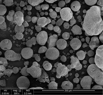
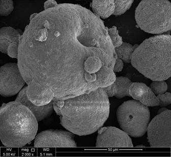
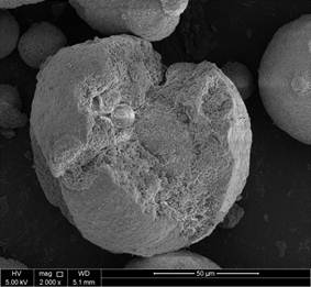
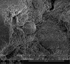
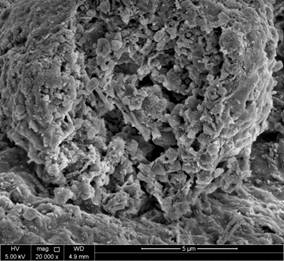
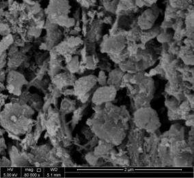
Figure 9. SEM images of fresh catalyst.
|
|
|
| a. Magnification 500x | b. Magnification 2000x |
|
|
|
| c. Magnification 5000x | d. Magnification 10,000x |
|
|
|
| e. Magnification 20,000x | f. Magnification 40,000x |
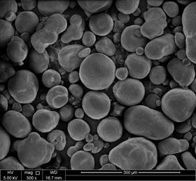
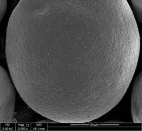
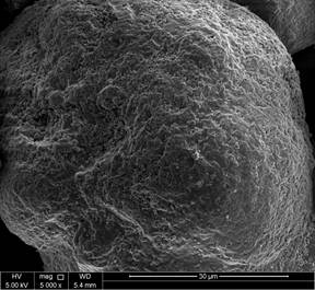
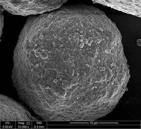
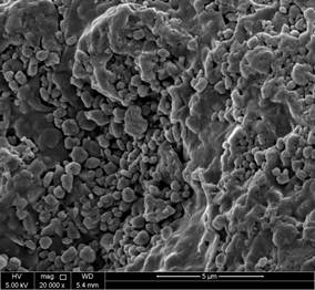
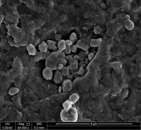
Figure 10. SEM images of spent catalyst.
4. Conclusion
Characterization of samples of fresh and spent FCC catalyst based on N2 adsorption/desorption measurements, indicate that most of pores consist of mesopores. The BET and t-plot methods provide the best fit of data whereas Langmuir, Freundlich and Temkin provided poor fit of data. There is also a clear fair agreement between both quantitative estimates based on BJH and DH for pore volume and surface area. The BET analysis shows a significant reduction of 60.79% in surface area and 21.34% in pore volume with respect to the fresh catalyst. SEM-EDS provide a wealth of information on particle structure and morphology. The cause of deactivation is clearly due to fouling, poisoning, dealumination and possibly sintering.
References
- N. Ravichander, T. Chiranjeevi, D. Gokak, R. Voolapalli, N. Choudary, FCC catalyst and additive evaluation—A case study. Catalysis Today, 2009, 141, 115-119.
- D. Rawlence, K. Gosling,FCC catalyst performance evaluation,Applied Catalysis, 1988, 2, 213–237.
- H. Cerqueira, G. Caeiro, L. Costa, F. RamôaRibeiro, F.2008.Deactivation ofFCC catalysts,Journal of Molecular Catalysis A: Chemical, 2008, 292, 1-13.
- R. Sadeghbeigi, Fluid Catalytic Cracking Handbook: Design, Operation and Troubleshooting of FCC Facilities, Gulf Publishing Company, Houston, TX, USA, 2000.
- J. Scherzer, Octane-Enhancing Zeolitic FCC Catalyst: Scinetific and Technical . Marcel Dekker, New York, 1990.
- M. Falco, E. Morgado, N. Amadeo, U. Sedran, Accessibility in alumina matrices ofFCC catalysts, Applied Catalysis A: General,2006,315,29-34.
- Q. Yan-ping, C. Sheng-li, D. Peng, X. Ke-qi, S. Bao-jian, Novel macroporous residua FCC catalysts, Journal of Fuel Chemistry and Technology, 2006, 34, 6, 685-690.
- D. Sun, X. Li, M. Brungs, D. Trimm, Encapsulation of heavy metals on spent fluid catalytic cracking catalyst, Water Science and Technology, 1998, 38, 4–5, 211-217.
- T. G. Petti, D. Tomczak, C. J. Pereira, W. Cheng,Investigation of nickel species on commercial FCC equilibrium catalysts-implications on catalyst performance and laboratory evaluation, Applied Catalysis A: General, 1998, 169, 1, 95-109.
- L. Wu, F. Khalil, G. M. Smith, B. Yilmaz, Jr. R. McGuire, Effect of solvent on the impregnation of contaminant nickel for laboratory deactivation of FCC catalysts, Microporous and Mesoporous Materials, 2015, 207, 195-199.
- G. Busca, P. Riani, G. Garbarino, G. Ziemacki, L. Gambino, E. Montanari, R. Millini, The state of nickel in spent Fluid Catalytic Cracking catalysts, Applied Catalysis A: General, 2014, 486, 176-186.
- M. Bendiksen, E. Tangstad, T. Myrstad, A comparison of laboratory deactivation methods forFCC catalysts,Applied Catalysis A: General, 1995, 129, 1, 21-31.
- M. Torrealba, M. Goldwasser, G. Perot, M. Guisnet, Influence of vanadium on the physicochemical and catalytic properties of USHY zeolite andFCC catalysts,Applied Catalysis A: General,1992,90, 1, 35-49.
- S. Yang, Y. Chen, C. Li, Metal-resistantFCC catalysts: effect of matrix, Applied Catalysis A: General, 1994, 115, 1, 59-68.
- E. Tangstad, M. Bendiksen, T. Myrstad, Effect of sodium deposition of FCC catalysts deactivation, Applied Catalysis A: General, 1997, 150, 1, 85-99.
- E. Tangstad, E. Myhrvold, T. Myrstad, A study on the effect of sodium chloride deposition on anFCC catalystin a cyclic deactivation unit. Applied Catalysis A: General, 2000, 193, 1–2, 113-122.
- US, 7456123 B2, (2008) W. Wachter.
- D. Wallenstein, B. Kanz, A. Haas, Influence of coke deactivation and vanadium and nickel contamination on the performance of low ZSM-5 levels inFCC catalysts,Applied Catalysis A: General, 2000, 192, 1, 105-123.
- BabitaBehera, S.S. Ray, Structural changes ofFCC catalystfrom fresh to regeneration stages and associated coke in a FCC refining unit: A multinuclear solid state NMR approach, Catalysis Today, 2009, 141, 1–2, 195-204.
- S. Haitao, D. Zhijian, Z. Yuxia, Tian Huiping, Effect of coke deposition on the remaining activity ofFCC catalystsduring gas oil and residue cracking, Catalysis Communications, 2011, 16, 1, 70-74.
- F. Pinto, A. Escobar, B. de Oliveira, Y. Lam, H. Cerqueira, B. Louis, J. Tessonnier, D. Su, M. Pereira, The effect of alumina onFCC catalystin the presence of nickel and vanadium, Applied Catalysis A: General, 2010, 388, 1–2, 15-21.
- G. Tonetto, J. Atias, H de Lasa,FCC catalystswith different zeolite crystallite sizes: acidity, structural properties and reactivity, Applied Catalysis A: General, 2004, 270, 1–2, 9-25.


