
International Journal of Advanced Materials Research, Vol. 1, No. 4, September 2015 Publish Date: Aug. 10, 2015 Pages: 120-125
Fatigue Endurance Under Rotating Bending and Torsion Testing, of AISI 6063-T5 Aluminum Alloy
Jorge L. ÁvilaAmbriz, Gonzalo M. Domínguez Almaraz*, Erasmo Correa Gómez, Julio C. Verduzco Juárez
Faculty of Mechanical Engineering, University of Michoacan (UMSNH), Morelia, Mexico
Abstract
In this paper is investigated the torsion and rotating bending fatigue endurance of AISI 6063-T5 aluminum alloy. Special attention was devoted to fatigue endurance reduction under torsion fatigue testing on this material. A torsion fatigue machine has been developed in our laboratory, which is under patent consideration. Torsion fatigue tests were carried out at frequency of 10 Hz and load ratio R = 0; whereas rotating bending fatigue tests were at 50 Hz and R = - 1. Results reveal a noticeable fatigue endurance reduction under torsion, compared to rotating bending loading. Fatigue life and crack propagation were analyzed for both fatigue testing modalities.
Keywords
Torsion Fatigue, Rotating Bending Fatigue, Aluminum Alloy, Fatigue Endurance, Crack Propagation
Received: July 5, 2015
Accepted: July 29, 2015
Published online: August 9, 2015
@ 2015 The Authors. Published by American Institute of Science. This Open Access article is under the CC BY-NC license. http://creativecommons.org/licenses/by-nc/4.0/
1. Introduction
The high potential of aluminum alloys like structural material requires the knowledge of mechanical properties; these alloys have been used in an increasing number of new structures and industrial applications, such as: antenna towers, aircraft structures, bridges, car industry, large-span geodesic domes, structures used with extremely low temperatures, etc. [1-3]. Furthermore it has been pointed out by several authors the potential use of aluminum alloys, which is not in accordance with benefits obtained nowadays by its application. In addition, the combination of a relatively high ratio of strength to self-weight, higher durability and availability, high corrosion resistance [4,5], and relatively low cost, makes aluminum alloys an excellent choice for a wide variety of industrial applications.
In order to assess the fatigue behavior of the 6063 – T5 aluminum alloy under torsion conditions, an experimental torsion fatigue machine was developed in our laboratory during 2014; this machine allows to performing static loading with only changing the start angle of testing. A principal contribution of this study concerns the torsion fatigue results compared to results under rotating bending fatigue, with similar stress amplitudes.
Physical and mechanical properties of aluminum alloys are of principal interest for industrial application: the use of cast aluminum alloys in automotive structural applications is growing rapidly because the need in reducing weight [6]; it is similar for the aircraft industry [7]. In recent works has been reported that the required torsion fatigue loading to induce mechanical failure in testing materials is lower compared to axial fatigue loading [8,9]. This result can be attributed to higher strain gradient or driving force in torsion specimens, compared to axial testing specimens. For the present study, a new torsion fatigue test machine [10], has been built up in our laboratory in order to obtain the results herein presented.
2. Materials and Methods
The general description of the developed torsion fatigue machine, Figure 1, is as follows:


Figure 1. Fatigue testing machine for torsion and torsion-bending testing (in process of patent, 2015).
• A servo-motor is used to communicate rotating motion to vertical or principal axis, through a chain and gear.
• The servo motor is controlled by a program developed with the "Robotis" platform, allowing communicating rotating motion with ± 0.09 degree of precision.
• Vertical axis connects with testing specimen through a free torsion chuck; the specimen bottom end is clamped by a second fixed chuck.
• A linear actuator allows communicating linear movement to the platform supporting the fixed chuck, in order to obtain torsion-bending fatigue testing.
• Automatic testing stop is achieved through electric current continuity: the servo-motor is controlled by electric current through the testing specimen: under torsion failure, current is interrupted along the specimen leading to stopping the servo-motor.
• The number of testing cycles is recorded by a time counter, which is connected to electric current continuity of testing specimen. Under torsion failure, current is interrupted and the time counter is stopped.
The chemical composition, in weight, and the principal mechanical properties of testing material are shown in Tables 1 a) and b), respectively. Test specimens for torsion fatigue and rotating bending fatigue with dimensions in millimeters are presented in Figure 2 a) and b), respectively. It should be noticed that rotating bending specimen' dimensions were different regarding the ISO 1143-2010 standardization, in order to induce high stress at the specimen neck section of 60, 70 80 and 90% the yield stress of this material. The rotating bending fatigue tests were obtained in a previous study [11], at frequency of 50 Hz and stress ratio R = -1. On the other hand, torsion fatigue tests were obtained recently at the frequency of 10 Hz, at room temperature, without control of environmental humidity and stress ratio R = 0. Concerning surface roughness, all specimens were machined similarly in order to maintain the roughness surface without large variation; the roughness parameter Ra (arithmetic average of absolute values) was close to 10 mm for all testing specimens.
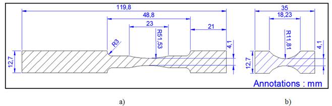
Figure 2. a) Specimens dimensions (mm) for rotating bending specimen, and b) for torsion specimen.
Table 1 a). Chemical composition in weight (%) for the 6063 – T5 aluminum alloy.
| Si | Fe | Cu | Mn | Mg | Cr | Zn | Ti | Al |
| 0.3 – 0.6 | 0.35 | 0.1 | 0.1 | 0.4 – 0.85 | 0.1 | 0.1 | 0.1 | >96.9 |
Table 1 b). Principal mechanical properties of the 6063 – T5 aluminum alloy.
| Elastic Limit | UTS | % | E Young | Hardness | Shear Modulus | Shear Strength |
| MPa | MPa | Elongation | GPa | Brinell | GPa | MPa |
| 145 | 187 | 0.33 | 68.9 | 60 | 25.8 | 117 |
This torsion fatigue machine is one of the world' fatigue machine capable of performing different tests: torsion, pure bending and combined bending-torsion. Figure 1 shows the servo-motor and the linear actuator that communicates the movement of torsion and flexion, respectively. Both of them have a power supply of 12 V DC and they are controlled by the CM-900 card; that is, an embedded board based on STMicroelectronics and its hardware and software of open source (Robotics is the software controlling the electronic card, it is supported in Windows, Mac OSX, and Linux for convenient and easy development of robotics), Figure 3. Concerning general aspects of Robotics programming, in Figure 3 b), the line: Dxl. Write Word (ID, Address, Value) indicates: ID-the actuator number, Address-the position identifications and Value-the final position. In this example, the position changes from 0 to 130.6 in intervals of 50 ms (the three programming rows in Figure 3 b). In addition, this fatigue machine has a led display showing the number of cycles of fatigue life in real time. Both, the cycles counter and the torsion machine are stopped simultaneously when the specimen is broken.
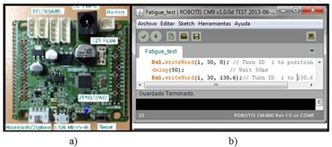
Figure 3. a) CM-900 card, b) Robotis CM9 v1.0.0d programming software.
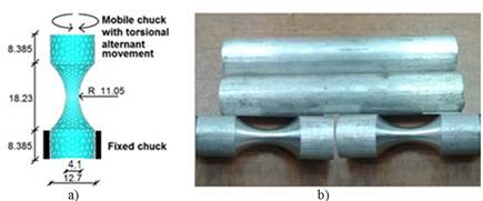
Figure 4. a) Shape, dimensions (mm), and constrains for torsion specimen, b) solid bars and manufactured specimens.
The narrow section of torsion specimen was close to 4.1 mm; no international standardization is available concerning torsion fatigue specimens; the norm ASTM A938-97 concerns the testing of a uniform section wire under torsion. The specimen profile was determined to induce a working stress at the specimen narrow section of 90, 80, 70, and 60% the shear stress of this material (117 MPa). Figure 4 a) shows the dimensions (mm) and constrains of the symmetric hourglass shape specimen used in torsion fatigue testing, and Figure 4 b) presents the manufactured hourglass shape specimen for torsion testing, from a solid bar.
3. Results
Figure 5 shows the experimental results for both modalities of testing fatigue; it is observed that torsion life is lower in regard to rotating bending fatigue life, for the four applied loads. The logarithmic tendency lines (red and blue) are not parallels; they converge for the low applying loading and diverge for high loading. In reducing the load, difference between the two modalities decreases; this result has been observed by some authors [12-14]. Furthermore, from theoretical point of view, a very low applied load should imply an infinite fatigue life for both modalities of testing. On the other hand in increasing loading, the difference between the shear stress in torsion and yield stress in rotating bending is at the origin of fatigue endurance variation.

Figure 5. Fatigue endurance of the 6063-T5 aluminum alloy, in rotating bending and torsion fatigue testing.
4. Discussion
Figure 5 shows that the rotating bending fatigue results (R= -1), in this aluminum alloy are close to 3 x 10⁵ cycles at 90% the elastic limit of this material; whereas at 90% of shear limit, fatigue life is close to 3000 cycles in torsion (R= 0). On the other hand for low applying loading, fatigue life is close to 7 millions of cycles for 60% the elastic limit of this material under rotating bending fatigue and 3.5 x 10⁵cycles under torsion fatigue, with 60% of shear stress limit.
Concerning the fracture surfaces, it is observed a principal and secondary crack path for rotating bending testing, Figure 6 a), perpendicular to the axial applying load. Under rotating bending fatigue of aluminum alloys, it is frequently observed a principal crack path and one or more simultaneous secondary crack paths which develop in competition with the first one [15,16].

Figure 6. a) Crack paths for rotating bending, and b) torsion fatigue testing.
Crack paths for torsion fatigue testing are shown in Figure 6 b). A ductile crack behavior is present in this material which is perpendicular to principal axis. In addition, it is observed an angular brittle crack behavior that develops simultaneously under an angle close to 45º in regard the specimen' principal axis.
The last result reveals the crack initiation and propagation behavior on an intermediate ductile-brittle material, such as this aluminum alloy, under torsion fatigue testing [17,18]. Crack propagation perpendicular to principal axis is related to ductile behavior under torsion fatigue loading [19]; whereas crack propagation with an angle close to 45º is associated with brittle behavior, under torsion fatigue loading [20].
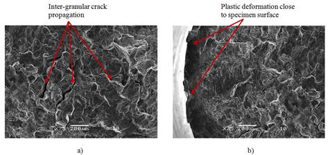
Figure 7. a) Inter-granular crack propagation at the specimen center under torsion loading, b) high plasticity deformation at the specimen neck section surface.
Fracture surfaces obtained by scanning electron microscope for the torsion fatigue testing are shown on Figure 7. Inter-granular fracture is observed at the center of testing specimen, Figure 7 a), and an important plastic deformation characterizes the zone close the specimen surface, Figure 7 b). These results are in accordance with the stress gradient under torsion loading: high stresses at the specimen surface and linear decrease in radial direction to the specimen center.
5. Conclusion
Rotating bending fatigue tests have been compared to torsion fatigue for aluminum alloy 6063-T5. For the high loading regime (90% of elastic and shear limit of this material), fatigue endurance under rotating bending (R= - 1) is one hundred times higher compared to torsion fatigue endurance (R= 0). Concerning the low loading regime (60% of elastic and shear limit of this material), fatigue endurance under rotating bending is only 20 times the corresponding to torsion testing. A torsion fatigue machine has been designed and developed to carry out the torsion fatigue testing.
Primary and secondary crack propagation paths are observed under rotating bending; whereas a combined ductile-brittle behavior on crack propagation is noticed on the torsion fatigue specimens. The torsion fracture surfaces show inter-granular crack propagation at the center of specimen, where the stress level is low compared to specimen' surface. Important plastic deformation is observed at the specimen surface (neck section), where the shear stress is higher.
Further investigations will be carried out in the next future, particularly the ductile-brittle crack propagation transition, the fatigue endurance variation between rotating bending and torsion on this aluminum alloy under the same loading rate, and investigations concerning the elastic limit and the shear strength effects on crack initiation and propagation on this aluminum alloy.
Acknowledgements
The authors wish to express their gratitude to the University of Michoacan for the facilities received during this study. A special mention of gratitude to the CONACYT (The National Council for Science and Technology, Mexico), for the financial support destined to this work by the program grant: CB- 241117-2014.
ORCID
Gonzalo M. Domínguez Almaraz
http://orcid.org/0000-0002-8786-8640
References
- Mazzolani, FM. Structural applications of aluminium in civil engineering. Structural Engineering International. 2006: 16(4); 280-285.
- Pan B, Jiang TM, Jin JM, M. Ma D. Failure Analysis of Aircraft Aluminum Alloy Structures in Coastal Environments. Advanced Materials Research. 2012: 430-432; 1509-1513.
- Sasaki K, Takahashi T. Low cycle thermal fatigue and microstructural change of AC2B-T6 aluminum alloy. Int. J. of Fatigue. 2006: 28(3); 203-210.
- Kciuk M, Tkaczyk S. Structure, mechanical properties and corrosion resistance of AlMg5 and AlMg1Si1 alloys. J. of Achiev.in Materialsand Manufact. Engineering. 2007: 21(1); 39-42.
- Ghali E. Corrosion Resistance of Aluminum and Magnesium Alloys (Understanding, Performance and Testing). Hoboken, New Jersey,John Wiley & Sons; 2010, 640 pages.
- Zhu X, Shyam A, Jones, JW, Mayer H, Lasecki, JV, and Allison, JE. (2006). Effects of microstructure and temperature on fatigue behavior of E319-T7 cast aluminum alloy in very long life cycles. Int. J. of Fatigue. 2006: 28(11); 1566-1571.
- Kermanidis, AT, Petroyiannis, PV, and Pantelakis, SG. Fatigue and damage tolerance behavior of corroded 2024 T351 aircraft aluminum alloy. Theor. and Appl. Fract. Mechanics. 2005: 43(1); 121-132.
- Li, RH, Zhang P, and Zhang ZF. Fatigue cracking and fracture behaviors of coarse-grained copper under cyclic tension–compression and torsion loadings. Mat. Scien. and Eng.: A. 2013: 574; 113-122.
- Akiniwa Y, Stanzl-Tschegg, S, Mayer H, Wakita M, and Tanaka.(2008). Fatigue strength of spring steel under axial and torsional loading in the very high cycle regime.Int. J. of Fatigue. 2008: 30(12); 2057-2063.
- Ávila Ambriz, JL, Domínguez Almaraz GM, Correa Gómez, E, and González Bernal, R. Fatigue Testing Machine for Developing Fatigue Tests Under Different Modes, Including: Rotating Bending, Torsion, and Its Combinations. J. of Mechatronics. 2014: 2(4); 246-250.
- Dominguez Almaraz, GM, Avila Ambriz, JL, and Cadenas Calderón E. Fatigue endurance and crack propagation under rotating bending fatigue tests on aluminum alloy AISI 6063-T5 with controlled corrosion attack. Eng. Fracture Mechanics. 2012: 93; 119-131.
- Mayer H, Schuller R, Karr U, Irrasch D, Fitzka M, Hahn M, Bacher-Höchst M. Cyclic torsion very high cycle fatigue of VDSiCr spring steel at different load ratios. Int. J. of Fatigue. 2015: 70; 322–327.
- Zhang J, Xiao Q, Shi X, FeiB. Effect of mean shear stress on torsion fatigue failure behavior of 2A12-T4 aluminum alloy. Int. J. of Fatigue. 2014: 67; 173–182.
- Mayer H. Ultrasonic torsion and tension–compression fatigue testing: Measuring principles and investigations on 2024-T351 aluminium alloy. Int. J. of Fatigue. 2006: 28; 1446–1455.
- Takahashi Y, Yoshitake H, Nakamichi R, Wada T, Takuma M, Shikama T, Noguchi H. Fatigue limit investigation of 6061-T6 aluminum alloy in giga-cycle regime. Materials Science and Engineering: A. 2014: 614; 243–249.
- Couteri H, Bellett D, Morel F, Agustins L, Adrien J. High cycle fatigue damage mechanisms in cast aluminium subject to complex loads. Int. J. of Fatigue. 2013: 47; 44-57.
- Liu S, Chao YJ, Zhu X. Tensile-shear transition in mixed mode I/III fracture. Int. J. of Solids and Structures. 2004: 41; 6147-6172.
- Campbell FC. Fatigue and Fracture: Understanding the Basis. Materials Park OH 44073-0002, ASM International 2012, 685 pages.
- Billington EW. Failure on ductile materials deformed in simple torsion. Eng. Fract. Mechanics 1981: 15(1-2); 21-37
- McClaflin D, Fatemi A. Torsional deformation and fatigue of hardened steel including mean stress and stress gradient effects. Int. J. of Fatigue 2004: 26; 773-784.


