
International Journal of Advanced Materials Research, Vol. 1, No. 2, May 2015 Publish Date: May 7, 2015 Pages: 25-31
Clamped Saddle Shells of Laminated Composites: Effect of Cutout on Natural Frequency and Mode Shapes
Sarmila Sahoo
Department of Civil Engineering, Heritage Institute of Technology, Kolkata, India
Abstract
Clamped saddle shells made of laminated composite materials in presence of stiffeners and cutouts are analyzed employing the eight-noded curved quadratic isoparametric element for shell with a three noded beam element for stiffener formulation. Free vibration problem of stiffened saddle shells with different size and position of the cutouts with respect to the shell centre are examined to find natural frequency and mode shapes of stiffened shells and arrive at some conclusions useful to the designers. The results are further analyzed to suggest guidelines to select optimum size and position of the cutout with respect to shell centre.
Keywords
Clamped Saddle Shell, Laminated Composite, Cutout, Natural Frequency, Mode Shape
Received: March 31 2015 / Accepted: April 15 2015 / Published online: May 5, 2015
@ 2015 The Authors. Published by American Institute of Science. This Open Access article is under the CC BY-NC license. http://creativecommons.org/licenses/by-nc/4.0/
1. Introduction
Laminated composites are increasingly being used nowadays in aerospace, civil, marine and other related weight-sensitive engineering applications requiring high strength-to-weight and stiffness-to weight ratios. Among the different shell forms, saddle shells are one of them. Cutouts are provided in shell panels to save weight and also to provide a facility for inspection. In practice the margin of the cutouts are stiffened to take account of stress concentration effects. Also, there can be some instruments directly fixed on these panels, and the safety of these instruments can be dependent on the vibration characteristics of the panels. Hence free vibration studies on saddle shell panels with cutouts are of interest to structural engineers.
Dynamic analysis of shell structures having complex geometry, loading and boundary conditions can be solved efficiently by finite element method. Different computational models for laminated composites were proposed by researchers. Chao and Tung [1] presented an investigation on the dynamic response of axisymmetric polar orthotropic hemispherical shells. Later free vibration study of doubly curved shells was done by Liew and Lim [2], Chakravorty et al. [3]. Sathyamoorthy [4] considered the nonlinear vibration of moderately thick orthotropic spherical shells. Gautham and Ganesan [5] considered free vibration characteristics of isotropic and laminated orthotropic spherical caps. Wang et al [6] studied wave propagation of stresses in orthotropic thick-walled spherical shells. Lellep and Hein [7] did an optimization study on shallow spherical shells under impact loading. Dai and Wang [8] analyzed stress wave propagation in laminated piezoelectric spherical shells under thermal shock and electric excitation. Dynamic stability of spherical shells was studied by Ganapathi [9] and Park and Lee [10]. Qatu et al [11] reviewed the work done on the vibration aspects of composite shells between 2000-2009 and observed that most of the researchers dealt with closed cylindrical shells. But, saddle shells on rectangular planform with cutout (stiffened along the margin) are far from the existing literature. Accordingly, the present study considers natural frequencies and mode shape of composite saddle shell with cutout (stiffened along the margin) with concentric and eccentric cutouts, and considers the shells to be clamped along all edges.
2. Formulation
A laminated composite saddle shell of uniform thickness h (Fig.1) and radius of curvature Rx and Ry is considered. Keeping the total thickness the same, the thickness may consist of any number of thin laminae each of which may be arbitrarily oriented at an angle q with reference to the X-axis of the co-ordinate system. The constitutive equations for the shell are given by:
{F}=[E]{e}
where, ![]() ,
,
 ,
,
![]() .
.
The force and moment resultants are expressed as

The strain-displacement relations on the basis of improved first order approximation theory for thin shell are as
where, the first vector is the mid-surface strain for a saddle shell and the second vector is the curvature.
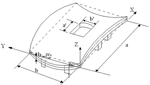
Figure 1. Schematic of saddle shell with concentric cutout and stiffeners
An eight-noded curved quadratic isoparametric finite element is used for saddle shell analysis. The five degrees of freedom taken into consideration at each node are u, v, w, a, b. The following expressions establish the relations between the displacement at any point with respect to the co-ordinates x and h and the nodal degrees of freedom.
![]() ,
, ![]() ,
, ![]() ,
, ![]() ,
, ![]()
The generalized displacement vector of an element is expressed in terms of the shape functions and nodal degrees of freedom as:
![]()
i.e., 
The strain-displacement relation is given by
![]() ,
,
where 
The element stiffness matrix is
![]()
The element mass matrix is obtained from the integral
![]() ,
,
where,
 ,
,
 ,
,
in which
 ,
, 
Three noded curved isoparametric beam elements are used to model the stiffeners, which are taken to run only along the boundaries of the shell elements. In the stiffener element, each node has four degrees of freedom i.e. usx, wsx, asx and bsx for X-stiffener and vsy, wsy, asy and bsy for Y-stiffener. The generalized force-displacement relation of stiffeners can be expressed as:
X-stiffener:![]() ;
;
Y-stiffener:![]()
where, ![]() ;
;
![]() ,
,
![]() ;
;
![]()
The sectional parameters are calculated with respect to the mid-surface of the shell by which the effect of eccentricities of stiffeners is automatically included. The element stiffness matrices are of the following forms.
for X-stiffener:![]() ;
;
for Y-stiffener:![]()
The integrals are converted to isoparametric coordinates and are carried out by 2-point Gauss quadrature. Finally, the element stiffness matrix of the stiffened shell is obtained by appropriate matching of the nodes of the stiffener and shell elements through the connectivity matrix and is given as:
![]() .
.
The element stiffness matrices are assembled to get the global matrices.
The element mass matrix for shell is obtained from the integral
![]() ,
,
where,
,
,
in which
,
The mass matrix of the stiffened shell element is the sum of the matrices of the shell and the stiffeners matched at the appropriate nodes.
![]() .
.
The element mass matrices are assembled to get the global matrices.
The code developed can take the position and size of cutout as input. The program is capable of generating non uniform finite element mesh all over the shell surface. So the element size is gradually decreased near the cutout margins. The free vibration analysis involves determination of natural frequencies from the condition.
![]()
This is a generalized eigen value problem and is solved by the subspace iteration algorithm.
3. Results and Discussion
The results of Table 1 show that the agreement of present results with the earlier ones is excellent and the correctness of the stiffener formulation is established. Free vibration of clamped saddle shells of (0/90)4 lamination with cutouts is considered. The fundamental frequencies of saddle shell with cutout obtained by the present method agree well with those reported by Chakravorty et al. [3] as evident from Table 1, establishing the correctness of the cutout formulation.
Table 1. Non-dimensional fundamental frequencies (![]() ) for laminated composite saddle shell with cutout
) for laminated composite saddle shell with cutout
| a//a | Chakravorty et. al.[3] | Present model |
| 0.0 | 113.567 | 112.926 |
| 0.1 | 97.753 | 98.041 |
| 0.2 | 97.599 | 97.032 |
| 0.3 | 111.489 | 111.033 |
| 0.4 | 110.210 | 110.20 |
a/b=1, a/h=100, a//b/=1, h/Rxx= -h/Ryy=1/300
In order to study the effect of cutout size and position on the free vibration response additional problems for clamped saddle shells with 0/90/0/90 and +45/-45/+45/-45 laminations have been solved. The positions of the cutouts are varied along both of the plan directions of the shell to study the effect of eccentricity of cutout on the fundamental frequency.
Table 2 furnishes the results of non-dimensional frequency (![]() ) of 0/90/0/90 and +45/-45/+45/-45 stiffened saddle shells with cutout. The shells considered are of square plan form (a=b) and the cutouts are also taken to be square in plan (a/=b/). The cutouts placed concentrically on the shell surface. The cutout sizes (i.e. a//a) are varied from 0 to 0.4. Cutouts are concentric on shell surface. The stiffeners are place along the cutout periphery and extended up to the edge of the shell. The material and geometric properties of shells and cutouts are mentioned along with the Table.
) of 0/90/0/90 and +45/-45/+45/-45 stiffened saddle shells with cutout. The shells considered are of square plan form (a=b) and the cutouts are also taken to be square in plan (a/=b/). The cutouts placed concentrically on the shell surface. The cutout sizes (i.e. a//a) are varied from 0 to 0.4. Cutouts are concentric on shell surface. The stiffeners are place along the cutout periphery and extended up to the edge of the shell. The material and geometric properties of shells and cutouts are mentioned along with the Table.
Table 2. Non-dimensional fundamental frequencies (![]() ) for laminated composite stiffened saddle shell for different sizes of the central square cutout and different laminations
) for laminated composite stiffened saddle shell for different sizes of the central square cutout and different laminations
| Laminations | Cutout size () | ||||
| 0 | 0.1 | 0.2 | 0.3 | 0.4 | |
| 0/90/0/90 | 93.08 | 107.18 | 129.7 | 135.35 | 138.56 |
| +45/-45/+45/-45 | 81.34 | 98.71 | 103.2 | 107.23 | 112.06 |
a/b=1, a/h=100, ![]() =1, h/Rxx=- h/Ryy=1/300; E11/E22 = 25, G23 = 0.2E22, G13 = G12 = 0.5E22, n12 =n21 =0.25
=1, h/Rxx=- h/Ryy=1/300; E11/E22 = 25, G23 = 0.2E22, G13 = G12 = 0.5E22, n12 =n21 =0.25
From Table 2 it is seen that when a cutout is introduced to a stiffened shell the fundamental frequency increases in all the cases. This increasing trend is noticed for both cross ply and angle ply shells. This initial increase in frequency is due to the fact that with the introduction of cutout, numbers of stiffeners increases from two to four in the present study. As the cutout grows in size the loss of mass is more significant than loss of stiffness, and hence the frequency increases. As with the introduction of a cutout of a//a=0.2, in shell surface, the frequency increases in most of the cases, this leads to the engineering conclusion that concentric cutouts with stiffened margins may be provided safely on shell surfaces for functional requirements upto a//a=0.2.
The mode shapes corresponding to the fundamental modes of vibration are plotted in Fig.2 and Fig.3 for cross ply and angle ply shells respectively. The normalized displacements are drawn with the shell mid-surface as the reference for all the support condition and for all the lamination used here. For clamped shells the fundamental mode shapes are complicated. With the introduction of cutout mode shapes remain almost similar. When the size of the cutout is increased from 0.2 to 0.4 the fundamental modes of vibration do not change to an appreciable amount.
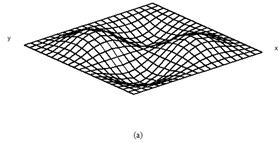
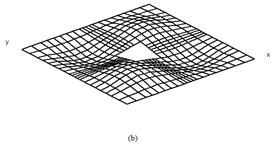
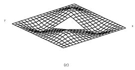
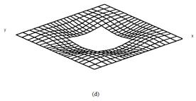
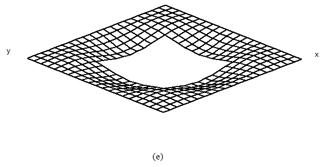
Figure 2. First mode shapes of laminated composite (0/90/0/90) stiffened saddle shell for different sizes of the central square cutout (a) ![]() =0, (b)
=0, (b) ![]() =0.1, (c)
=0.1, (c) ![]() =0.2, (d)
=0.2, (d) ![]() =0.3, (e)
=0.3, (e) ![]() =0.4
=0.4
The effect of eccentricity of cutout positions on fundamental frequencies, are studied from the results obtained for different locations of a cutout with a//a=0.2. The non-dimensional coordinates of the cutout centre was varied from 0.2 to 0.8 along each directions, so that the distance of a cutout margin from the shell boundary was not less than one tenth of the plan dimension of the shell. The fundamental frequency of a shell with an eccentric cutout is expressed as a percentage of fundamental frequency of a shell with a concentric cutout. This percentage is denoted by r in Table 3. It can be seen that eccentricity of the cutout along the length of the shell towards the edges makes it more flexible. It is also seen that almost all the cases r value is maximum in and around central position. It is noticed that for clamped saddle shells the maximum fundamental frequency always occurs along the diagonal of the shell. This table indicates the maximum eccentricity of a cutout which can be permitted if the fundamental frequency of a concentrically punctured shell is not to reduce a drastic amount.
Table 3. Values of ‘r’ for clamped saddle shells
| Lamination | ||||||||
| 0.2 | 0.3 | 0.4 | 0.5 | 0.6 | 0.7 | 0.8 | ||
| 0/90/0/90 | 0.2 | 91.20 | 85.18 | 88.20 | 91.75 | 88.17 | 85.18 | 85.03 |
| 0.3 | 84.39 | 85.22 | 89.00 | 93.85 | 89.00 | 85.22 | 84.39 | |
| 0.4 | 86.94 | 88.31 | 92.41 | 96.84 | 92.41 | 88.31 | 86.94 | |
| 0.5 | 90.16 | 91.96 | 96.15 | 100.00 | 96.15 | 91.96 | 90.16 | |
| 0.6 | 86.94 | 88.31 | 92.41 | 96.84 | 92.41 | 88.31 | 86.94 | |
| 0.7 | 84.39 | 85.22 | 89.00 | 93.64 | 89.00 | 85.22 | 84.39 | |
| 0.8 | 84.76 | 84.97 | 88.01 | 91.77 | 88.13 | 85.07 | 87.34 | |
| +45/-45/+45/-45 | 0.2 | 62.14 | 67.01 | 74.35 | 81.73 | 74.25 | 66.95 | 62.10 |
| 0.3 | 66.84 | 72.12 | 79.94 | 87.32 | 79.80 | 72.03 | 66.79 | |
| 0.4 | 73.89 | 79.66 | 87.87 | 94.77 | 87.69 | 79.53 | 73.81 | |
| 0.5 | 80.79 | 86.62 | 94.42 | 100.00 | 94.42 | 86.62 | 80.79 | |
| 0.6 | 73.81 | 79.53 | 87.69 | 94.77 | 87.87 | 79.66 | 73.89 | |
| 0.7 | 66.79 | 72.03 | 79.80 | 87.32 | 79.94 | 72.12 | 66.84 | |
| 0.8 | 62.10 | 66.94 | 74.23 | 81.72 | 74.34 | 67.00 | 62.13 | |
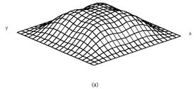
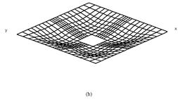
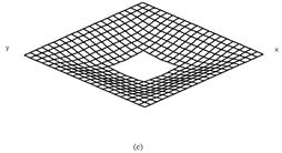
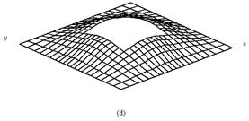
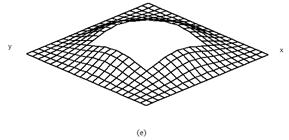
Figure 3. First mode shapes of laminated composite (+45/-45/+45/-45) stiffened saddle shell for different sizes of the central square cutout (a) ![]() =0, (b)
=0, (b) ![]() =0.1, (c)
=0.1, (c) ![]() =0.2, (d)
=0.2, (d) ![]() =0.3, (e)
=0.3, (e) ![]() =0.4
=0.4
4. Conclusions
Present results are in close agreement with those of the benchmark problems. Thus the finite element code used here is suitable for analyzing free vibration problems of stiffened saddle panels with cutouts. The relative free vibration performances of shells are expected to be very useful in decision-making for practicing engineers. The information regarding the behavior of clamped stiffened saddle shell with eccentric cutouts for a wide spectrum of eccentricity for cross ply and angle ply shells may also be used as design aids for structural engineers.
References
- Chao, C. C., & Tung, T. P. (1989). "Step pressure and blast response of clamped orthotropic hemispherical shells". International Journal of Impact Engineering, 8(3), 191-207.
- Liew, K. M., & Lim, C. W. (1995). "Vibration behaviour of doubly-curved shallow shells of curvilinear planform". ASCE Journal of Engineering Mechanics, 121(12), 1277-1283.
- Chakravorty, D., Sinha, P. K., & Bandyopadhyay, J. N. (1995). "Free vibration analysis of point supported laminated composite doubly curved shells- a finite element approach". Computers and Structures, 54(2), 191-207.
- Sathyamoorthy, M. (1995). "Nonlinear vibrations of moderately thick orthotropic shallow spherical shells". Computers and Structures, 57(1), 59-65.
- Gautham, B. P., & Ganesan, N. (1997). "Free vibration characteristics of isotropic and laminated orthotropic spherical caps". Journal of Sound and Vibration, 204(1), 17-40.
- Wang, X., Lu, G., & Guillow, S. R. (2002). "Stress wave propagation in orthotropic laminated thick-walled spherical shells". International Journal of Solids and Structures, 39, 3027-4037.
- Lellep, J., & Hein, H. (2002). "Optimization of clamped plastic shallow shells subjected to initial impulsive loading." Engineering Optimization, 34, 545-556.
- Dai, H. L., & Wang, X. (2005). "Stress wave propagation in laminated piezoelectric spherical shells under thermal shock and electric excitation." European Journal of Mechanics A/Solids, 24, 263-276.
- Ganapathi, M. (2007). "Dynamic stability characteristics of functionally graded materials shallow spherical shells." Composite Structures, 79, 338-343.
- Park, T., & Lee, S. Y. (2009). "Parametric instability osf delaminated composite spherical shells subjected to in-plane pulsating forces". Composite Structures, 91, 196-204.
- Qatu, M. S., Sullivan, R. W., & Wang, W. (2010). "Recent research advances on the dynamic analysis of composite shells:2000-2009". Composite Structures, 93, 14-31


