
American Journal of Mobile Systems, Applications and Services, Vol. 1, No. 2, October 2015 Publish Date: Sep. 1, 2015 Pages: 124-131
Tripod Robot Sorting System Based on Dynamic Programming Algorithm Design
Wang Hongmei*, Zhao Xueliang, Du Haitao
College of Information Engineering, Taishan Medical University, Taian, China
Abstract
The study is on the tripod robot, and the sorting system of industrial robot is designed. The key problem to be solved is the recognition, localization and path planning. For the identification and positioning of the workpiece, the main application is image processing technology and the many kinds of processing methods such as threshold segmentation, edge detection, contour detection, etc. are used, based on VS2013 embedded development platform OpenCV function library. For path planning, the use of a dynamic programming algorithm is made. Finally, the officially provided B & R Robotic Visualization and VNC viewer software co-simulation for simulation algorithm, which has achieved very good results.
Keywords
Sorting, Edge Detection, Path Planning, Dynamic Programming Algorithm
Received: August 5, 2015
Accepted: August 20, 2015
Published online: September 2, 2015
@ 2015 The Authors. Published by American Institute of Science. This Open Access article is under the CC BY-NC license. http://creativecommons.org/licenses/by-nc/4.0/
1. Introduction
Objects, in industrial production, often need to be picked up and placed in the new position. This kind of work is a single action but is repeated, so it is easily causes fatigue, difficult to ensure fast and accurate completion. But the Tripod robot system can easily accomplish this kind of work, and its accuracy and speed are unmatched. Compared with the traditional mechanical sorting activities, the robot sorting based on machine vision has wide adaptation, and has the advantage of changing the operation object and the sorting process at any time. At present, the machine vision technology has been developed gradually from the initial laboratory to the practical application stage. For example, the Suez Canal University developed a vision based on automatic sorting system 1, being able to pick up potatoes quickly and accurately according to the size of the potatoes. Southern Methodist University have developed a laser welding system based on machine vision, which can adjust the position of the welding adaptively real-time monitoring 2.The design of this article is based on machine vision industrial robots sorting system, using OpenCV to build a platform for sorting simulation. The basic process of whole system is: pictures are taken by the camera installed on the top of the work platform. The geometry of the platform is identified and its coordinate position is obtained through the image taken. Through coordinate control each geometry is picked up and put in the right place by the robot Tripod. The whole system is divided into the two parts of the hardware and the software.
2. Hardware Components of the System
The hardware system is composed of three parts: workpiece platform, vision system and robot control system. The workpiece platform unit is mainly used to put in place artifacts needed to sort, and this article mainly has three different colors and shapes of workpiece: yellow, orange and blue, triangles, circles and pentagram. The vision system is mainly composed of CCD camera, the bracket of the camera and visual processing software. The robot control unit is mainly responsible for receiving and analyzing the parameters received and controlling the operating hand to complete the sorting, grabbing and placing of the targeted artifact.
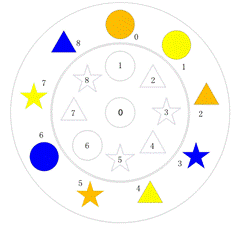
Figure 1. Top view of the platform at a certain point.
3. Problems of the Software and Solutions
3.1. Description of the Problem
All the geometries are placed on the outer ring, and the order is arbitrary. The position of the ring is consistent with that of the inner circular hole, that is, the angle between the geometrical body and the inner hole is zero. The camera’s image is required to be able recognize each geometry and obtain the coordinates, and the tripod grabs nine geometric bodies and put them back into the inner circle, with the geometry of the same colour being together, and the colour right in the circular center is not specifically required. The optimal grasping order is designed, to take the shortest possible time to put the geometry back to the inner ring of the corresponding position.
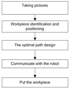
Figure 2. Flow chart of the solution.
3.2. Solutions
To achieve the goal, the whole problem can be divided into the following several steps: photo taking, image processing, path optimization, sending optimized path to the Tripod robot through the TCP/IP communication with Tripod robot and concluding of the optimization of the path. The flow chart of the specific implementation is as follows:

(a) The original shooting

(b) Renderings after correction
Figure 3. Image correction before and after comparison.
3.2.1. Image Correction
Since the image is oblique shot, a linear distortion of the image is obtained, which cannot directly identify and obtain accurate coordinates of the geometry, so it is necessary to correct the image. The specific method is as follows: the use of OpenCV cvGoodFeaturesToTrack () function is made for corner detection of the image, the statement is used to detect the filtered angular point, the location of the diagonal square four point coordinates are read, and standard square four point coordinates are given. Using CVGetPerspectiveTransform () function, the transformation matrix of a 3*3 between four vertices of the oblique beat and the standard square is obtained. Finally using cvWarpPerspective() function according to the transformation matrix, the perspective transformation is obtained, and then the image can be corrected.
3.2.2. The Pretreatment of the Image
In the corrected images, cvCvtColor () function image processing (Figure 5- a) is used for gray processing, and using cvThreshold () function, the gray images are processed for the two values (Figure 5-b), and then cvSmooth () function of Gauss smoothing for grayscale (as shown in figure 5-c) is made to reduce the image noise or distortion for more accurate barycentric coordinates. The use of cvCanny () function is made for image contour detection, and finally cvDilate () function is used to enhance the contour of the image edge detection (Figure 5-d), which makes the image contours more clearly and easier for complete recognition of the geometry for the following.
Figure 4. The flow chart of image preprocessing.


(a) Gray image (b) Binarizedimag (c) Gauss smoothed image (d) Enhanced image
Figure 5. Image preprocessing rendering.
3.2.3. The Identification of the Object Shape
The early stage of the target identification needs to be completed for the target extraction of the image with a certain feature or the parts that are particularly concerned. There are many kinds of methods for target extraction, including the edge method, region extraction and threshold segmentation, etc.4
(1) Identification of a circular
Because the corner for circular workpiece does not exist, the use of the Hough transform to identify the circular is an effective identification method for circular target. Hough Transform principle is as follows: by the use of correspondence between image space and parameter space, the simple statistics is accumulated in the parameter space to complete inspection tasks, and the edge of the boundary curve that is not continuous is linked, this method has a strong anti-noise characteristic to identify round workpieces5.
After smoothing images, cvHoughCircles () function is used to limit pixel error and radius of conditions, to find out the inner circle and six small circles respectively, and at the same time obtain the corresponding center coordinates and radius of the data. Finally cvCircle () is used totrace the image circle round function and contour.
(2) Triangle and star identification
Canny edge detection algorithm can be applied to detect the difference between the pixels based on the pixel contour boundaries, but it does not have to be profiled as a whole 3. In OpenCV, the profile is represented by the use of a binary tree, in order to facilitate the recovery profile. If the outline of a polygon is to be drawn or the shape to be analyzed, the method of the specified polygon precision curve is usually used for the approximation to the outline saved, the purpose of which is to get close to angular point and the target contour.
For the loaded binarized images, the cvCanny () function loading is used for the image edge detection of the outline of the image pattern; secondly by the use of cvDilate () function, the image will be enhanced after the edge detection, so the image’s outlines is clearer and more complete; after the use of cvFindContours () function from the binary image through enhanced retrieve profile, the contour is detected and then returns to the detected contour number. The use of cvApproxPoly () function is made to approximate the outline of a triangle and pentagram, and then the use of cvMoments () function is made to obtain the centre of gravity of the polygon according to the polygon outline coordinate, and the outline of the polygon detected is drawn according to cvPolyLine () function.
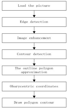
Figure 6. Triangle and pentagram identification flow chart.
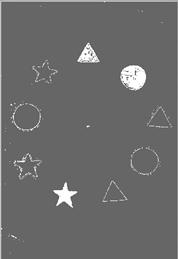
Figure 7. Effect of shape recognition.
3.2.4. The Colour Recognition of the Object
The cvGet2D () function is used to read, decompose and output G, B, R three color components of the pixel points, and then the color of the pixel point is determined according to the conditional statement, that is, the color of the geometry. (Note: the specific RGB components of each color in the sentence are shown in the following table.)
Table 1. Values for the RGB components.
| color | R | G | B |
| blue | (0,50) | (30,120) | (100,255) |
| orange | (190,255) | (30,160) | (0,75) |
| yellow | (200,255) | (130,255) | (10,75) |
3.3. Path Optimization
3.3.1. Dynamic Programming Algorithm
Dynamic programming is a branch of operations research, and it is a mathematical method to solve the optimization of decision making process. In the research on the optimization problem of multi-stage decision process in the early 1950s, American mathematician R.E. Bellman and others proposed the famous principle of optimization that the multi-stage process is divided into a series of single phase problems which are be solved one by one, and a new method is created to solve the problem of this kind of process optimization -- dynamic programming.
The basic idea of dynamic programming algorithm is as follows: the problem to be solved is decomposed into several interconnected sub-problems, the sub-problems are first solved, and then the solution to original problem is obtained from these sub-problems and the solution to the recurring problem is kept when encountered and solved for the first time, and the direct reference is used when the problem is met again. Dynamic programming algorithm for the results of a series of decisions, is different from the greedy algorithm in that in the greedy algorithm, a greedy criterion is used to make an irrevocable decision according to the solution of the problem; but in the dynamic programming algorithm, each optimal decision sub sequence is also examined, that is, whether there is a sub optimal structural property.
3.3.2. Greedy Algorithm
Greedy algorithm (also called greedy algorithm) is also one of the effective method to solve the problem of the shortest path. It is to point out the initial state of the problem, through a number of times of the greedy choice to get the optimal value (or better solution) of a problem solving method. It is to point to, in the problem solving, always made in the current appears to be the best choice. That is to say, not as a whole on the optimal into consideration, it is made only in a certain sense of local optimal solution. It is not on all issues to be the overall optimal solution, but the scope of a number of problems it can produce the overall optimal solution or approximate solution of the overall optimal solution.
3.3.3. The Comparison of Two Algorithms
Compared with the dynamic path planning method, the greedy algorithm does not divide the decision-making stage, but only pay attention to the nearest distance in the next step. So the greedy algorithm is suitable for the non-decision stage. If only pay attention to current but not in stages, will inevitably lead to the final result is not optimal. In solving the problem of repeated processing a state of dynamic programming algorithm is faster than the greedy algorithm .Therefore, this design uses the dynamic programming algorithm to realize the optimal path planning.
3.3.4. Concrete Implementation Steps
With the idea of dynamic programming drawn on, the planning process is divided into two stages:
First stage: The shortest path of the same shape of geometry in the outer circle when put in the corresponding position of the inner circle is calculated, that is, the calculation of the best placement of computational geometry, so as to ensure the shortest whole distance of the same geometry between the three starting points to the finish line position.
The second stage: The distance of the geometry between the coordinates in the circle and those in the outer ring can be obtained through calculation. The shortest distance is found by comparison. If the geometry located in the shortest distance is not grabbed, the geometry should be grabbed, and if a geometry is grabbed, look for the nearest geometry in addition to the one grabbed and determine whether it is grabbed, until you find the geometry that is not grabbed in the shortest distance in the outer ring from this position, and then the order of the geometry to be grabbed is determined according to the decision that is made in the first phase.
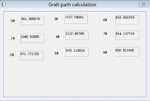
Figure 8. The calculations of path distance.
According to the principle of dynamic path planning, it is known that if the robot can ensure that the path of every step of the robot is the shortest, then the total path must be the shortest. In the first phase, the position corresponding to each starting point is determined, and the same is ensured that the three same geometries are moved by the outer loop to the inner circle. However, this does not guarantee the shortest path all the geometry moves from the outer ring, and the cause of the total path difference is the different order in which robot grabs the geometry. This paper discusses the geometries on the outside ring 0 # and 8 # respectively to be grabbed for the first time, and after calculation is done according to the above method, the shortest paths of the nine geometries are found out in relation with the fetching order. And then the comparison of the nine paths is made to locate the grabbing of the geometry for the first time.
For the convenience of description, take the grabbing of the ring 6# for example. The outer ring starting point of the location of the 6# is deposited on ID_start [6] (ID_start [0]-[8] is placed in the order respectively in the yellow triangle, orange triangle and blue triangle, yellow round and orange round and blue round, yellow star, orange star and blue star. The 6# yellow star is in ID_start [6]). After the first step in computing, outer ring # 6 of the optimal terminal location is in ID_end [6], # 3 is the internal circle obtained by calculating distance nearest in round 3 #, and the position has not been grabbed. The outer ring of 2 #, outer 2 # is the yellow triangle, its starting location in ID_start [0] is in round 2 #, the nearest distance in round 2 # is obtained by calculation, but the location of the grabbing has not been there. According to this method, we can get the path needed to grab the outer ring 6#: the outer ring outside the 6#-> inner circle 3#-> outer 2#-> inner circle 2#-> outer 1#-> inner circle 1#-> outer 0#-> inner circle 7#-> outer 7#-> inner circle 6#-> outer 5#-> inner circle 5#-> outer 4#-> inner circle 4#-> outer 3#-> inner circle 0#-> ring 8#-> round 8#. The rest of the geometry of the grab target outside the ring to be grabbed for the first time are consistent with the above, so it is not necessary to repeat.
From the analysis above, since the nearest point not to be grabbed is always looked for each time, once the first clamping position is determined, the order of the rest to be grabbed is determined. Therefore, retrieving the total path length mainly depends on the position of the first grab. The total distance is calculated between scratching 0 # and the first 9 # respectively from the first time, the figure 8 is the calculation of the total distance mobile robots move in this paper, and the shortest path is found through the comparison. That is, once the grab location can be determined for the first time, the program will automatically search the rest of the order. The concrete implementation process is shown in figure 9.
Through the program verification, dynamic path planning algorithm path distance is shorter than greedy algorithm calculation. Figure 10 and 11 are respectively using the greedy algorithm and dynamic programming algorithm to calculate the path.
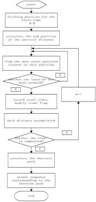
Figure 9. The flow chart of the implementation of the algorithm.
Five-pointed star, for example, greedy algorithm to get the position of the pentagramis: 8-8, 6-5, 5-3, dynamic programming algorithm to get the position of the pentagram is: 8-8, 6-3, 5-5, after calculation, the distance is shorter than the greedy algorithm for more than 100 pixels. When order more chaos, the advantage of dynamic path planning will be more obvious.
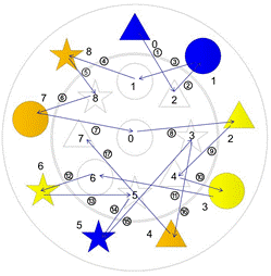
Figure 10. The path using greedy algorithm.
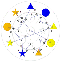
Figure 11. The path using dynamic programming algorithm.
4. Summary
With the development of industrial automation technology, the industrial robot trend to replace manual operation is inevitable, which lead to the broad and deep development of robot technology. And the traditional concept of the robot is just about avoiding the repeated labor and human does not have the ability of error correction and adaptive. With the continuous development of technology, today's mainstream online robot has basically closed-loop control and artificial intelligence, and even some high-end robot also has the self-learning ability. And this design is put forward in this background, and the main technical route is as follows:
(1) For image processing, a variety of image processing means in the combination of other methods are used, such as image gray processing, image processing, image binarization threshold processing, edge detection, contour detection, etc., so as to realize the recognition of the object shape, color and object orientation, etc.
(2) Path optimization is the most important and difficult part of the whole Triop robot control, which directly determines how much the robot is used for sorting. In this paper, the dynamic programming method is used based on the path optimization strategy, which is divided into two stages. In the first stage for dimension 9 (nine geometry), three decision variables can be obtained, and the decision variables are the three types of shape geometry placed. The second stage is in similar to that of the dimension 9, a decision variable, namely geometry of optimal grasping order is obtained. The algorithm provided by the official co-simulation software has been validated, and more than 2s in the grab time is saved in the first question compared to the given demo program.
Using dynamic programming algorithm of sorting system, in terms of path planning to calculate the shortest path than the more commonly used greedy algorithm with the advantages of fast speed. But this system’s problem in the image preprocessing stage is influenced by the outside light is larger, it is also need to improve in the future.
References
- Gamal ElMasry,Sergio Cubero,Enrique Moltó. In-line sorting of irregular potatoes by using automated computer-based machine visionsystem[J].Journal of Food Engineering,2012,112: 60-68.
- Huang W,Kovacevic R.Development of a real-time laser-based machine vision system to monitor and control welding processes [J].IntJAdvManufTechnol,2012,10:190-201.
- Liu Zhenyu, Li Zhongsheng, Zhao Xue, ZouFengshan. Industrial robots sorting based on machine vision technology research [J]. Journal of manufacturing automation, 2013,09 (top): 25.30.
- MouHaiRong. Industrial robots sorting based on machine vision technology research [J]. Science and technology innovation, 2014,16,55.
- Li Ting, Liu Ning. Round positioning technology based on machine vision research [J]. Computer engineering and application, 2012, (9): 153-156.
- Gaoxiang, guoweidong. Indoor mobile robot path planning algorithm [J]. Journal of mechanical engineering and automation, 2015, 2 (1): 168-170.
- CaiYaoyi. Harris corner matching and image fusion algorithm based embedded image system design [J]. Journal of computer applications and software. 2015, 32 (5): 220-223.
- Huang Weiguang,Dong Anguo. Camera self-calibration based on particle swarm algorithm [J]. Computer software and applications, 2015, 32 (5): 216-219.
- Steger C.Occlusion,clutter,and illumination invariant object recognition[J].International Archives ofPhotogrammetry Remote SensingandSpatialInformation Sciences,2002,34(:3/A):345-350.
- Barinova.O,Lempitsky.V,Kholi.P.On Detection of Multiple Object Instances Using Hough Transforms[J].Pattern Analysis and Machine Intelligence,2012,34(9):773-784.


