
American Journal of Mobile Systems, Applications and Services, Vol. 1, No. 2, October 2015 Publish Date: Jul. 25, 2015 Pages: 82-93
Enhancement of Network Performance of an Enterprises Network with VLAN
Isiaka A. Alimi1, *, Akeem O. Mufutau2
1Department of Electrical and Electronics Engineering, School of Engineering and Engineering Technology, Federal University of Technology, Akure, Nigeria
2Computer Resource Centre (CRC), Federal University of Technology, Akure, Nigeria
Abstract
The network performance can be significantly enhanced when the network broadcast domain is segmented into separate Layer 2 broadcast domains because, if a broadcast is not well contained in a network, it may lead to collision. Virtual local area network (VLAN) is a viable technology for broadcast containment in switched networks by logical segmentation. The network virtualization leads to ease of administration, confinement of broadcast domains, reduced broadcast traffic, as well as enforcement of security policies. This paper presents the benefits of network virtualization through the implementation of VLAN. Furthermore, practical application of VLAN for logical network segmentation based on job types is presented. Moreover, the implementation of an IEEE 802.1Q trunking protocol frame-tagging mechanism which enables multiple VLANs’ traffic between devices over the trunk link is considered.
Keywords
Trunk, Access, Link, Layer, Encapsulation, VLAN
Received: July 7, 2015 / Accepted: July 12, 2015 / Published online: July 24, 2015
@ 2015 The Authors. Published by American Institute of Science. This Open Access article is under the CC BY-NC license. http://creativecommons.org/licenses/by-nc/4.0/
Contents
1. Introduction 2. Virtual Local Area Network (VLAN) 3. VLAN Memberships 3.1. Layer 1 VLAN: Membership Based on Port 3.2. Layer 2 VLAN: Membership Based on MAC Address 3.3. Layer 2 VLAN: Membership Based on Protocol Type 3.4. Layer 3 VLAN: Membership Based on IP Subnet Address 3.5. Higher Layer VLAN 4. VLAN Connection 4.1. Access Link 4.2. Trunk Link 5. VLAN Identification 6. Experimental Implementation Results and Analysis 6.1. Experiment 1: VLAN Network Segmentation 6.2. Experiment 2: IEEE 802.1Q Trunking 7. Conclusions
1. Introduction
A local area network (LAN) is a group of computers that are connected together in a small geographic area to communicate with one another through wired or wireless link and share resources such as printers and network storage [1]. The LAN is able to provide network services and applications to people within a common managerial structure such as home, office building, campus or region. There are different LAN standards such as the Ethernet, Token Ring and Wireless LAN that can be employed in a network, however, the Ethernet that is based on the IEEE 802.3 technology and the Wireless LAN (Wi-Fi) which is based on the IEEE 802.11 technology are the most commonly used technologies.
A LAN has various advantages such as reduction in operational costs by its ability to efficiently support multipoint-to-multipoint (MP2MP) services instead of relying on separate technologies, high system availability, minimized downtime, sharing of sensitive information securely and reliably over the network that can affect an organization’s productivity significantly [2], [3]. However, there is an issue with the LAN when different levels of security and access are required by different network groups in an organization. This segregation problem can be addressed by separating different network groups physically in the network. However, this approach is not cost effective and relatively difficult to manage as the network grows in size and thereby prevents network scalability [4]. Employment of Virtual Local Area Network (VLAN) to achieve network segregation has been observed as viable solution [5], [6]. Figure 1 shows a traditional approach to LAN segmentation.
This paper investigates the network virtualization by the implementation of the VLAN as well as its associated benefits. The VLAN concepts for switched networks and the obtainable improvement of network virtualization by the implementation of the VLAN are presented in Section 2. Also, static and dynamic ways of realizing the VLAN memberships are discussed in Section 3. Section 4 focusses on means of connecting with the VLAN and the associated VLAN traffic that can be carried by each link. The types of VLAN encapsulation that can be employed to convey data from multiple VLANs over the trunk links with emphasis on the most widely used IEEE industry-standard trunking protocol are discussed in Section 5. Section 6 presents practical application of VLAN for logical network segmentation based on job types and the implementation of an IEEE 802.1Q trunking protocol. Some concluding remarks are given in Section 6.
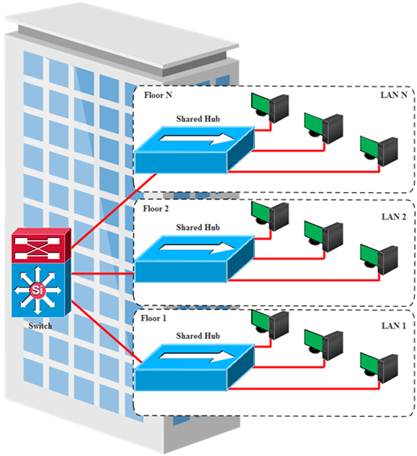
Figure 1. Traditional LAN Segmentation.
2. Virtual Local Area Network (VLAN)
In networking, a LAN has a single broadcast domain and the traffic from a workstation reaches other workstations on the LAN through the broadcast [4], [7]. This is not desirable as certain classified information can be received by unauthorized parties. Also, if the broadcast is not well contained, it can lead to collision in the network [6]. Therefore, network managers normally prevent the broadcasts from leaving a LAN with the aid of routers. However, routers are more expensive and usually take more time to process the incoming data compared to switches. In the light of this, Virtual Local Area Network (VLAN) has been developed as an alternative solution to using routers to contain broadcast traffic within a LAN [4], [8]. Nevertheless, routers are employed in the VLAN topologies for broadcast filtering, address summarization and traffic flow management [8].
A VLAN is a switched network that is logically segmented based on features such as service requirement, workgroup and protocol or application requirement rather than on a physical or geographical proximity. With the implementation of VLAN, geographically dispersed workstations, servers and other peripheral devices used by a particular workgroup can be put on the same VLAN and communicate as if they are physically on the same location in the network [8], [9], [10]. This enables the network administrators to manage the network without the need for running new cables or making major changes in the network infrastructure. Therefore, VLAN addresses scalability, flexibility, security, and network management issues which are associated with the traditional LAN [5], [7], [9], [10], [11], [12].
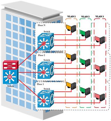
Figure 2. VLAN based LAN segmentation.
Devices on different switch ports can be assigned to different logical LANs with the help of VLAN. Also, switch in a network can be configured with multiple VLANs however, each switch port can be assigned to only one VLAN at a time. Each port of the switch that will be a member of a VLAN can be configured and the ports in the same VLAN are members of that particular VLAN. This configuration allows only ports that are in a VLAN to receive the broadcasts or information that is destined for that specific VLAN and ports that are non-member will not receive the information [6], [13]. Furthermore, the workstation that is connected to a port on the switch will automatically have membership to the VLAN which the port is assigned and will not be able to communicate with workstations in different VLANs despite the fact that they are connected to the same physical switch. Consequently, this is a security measure to control traffic within the VLAN as well as load-balancing network traffic. Therefore, the broadcast traffic can be contained effectively with the VLAN and the inherent bandwidth wastage of the traditional switched networks is prevented. This results in system performance enhancement [8]. Figure 2 shows a VLAN based LAN segmentation. Furthermore, the VLAN membership is divided into three main categories which are based on port, MAC address, and protocol type [4].
3. VLAN Memberships
There are two main ways by which the VLAN membership can be realized. The switch ports can be assigned to different VLAN in order to realize the membership [6]. This approach is known as static VLAN. Furthermore, the host devices’ MAC addresses can be assigned into a database and with the configuration of the switch, the host will be automatically mapped to the required VLAN. This approach is known as dynamic VLAN [11], [12]. In general, VLAN membership can be realized at different layer of the protocol stack, however, according to the 802.1Q standard, a network is limited to have 4096 VLANs and each switch is restricted to support 300-500 VLANs [5], [8], [14].
3.1. Layer 1 VLAN: Membership Based on Port
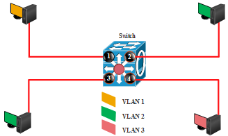
Figure 3. Port based VLAN Membership.
The physical layer VLAN membership is based on the ports on the switch that the workstations are connected to. This is a type of static VLAN in which the port number determines the associated VLAN [11]. This VLAN membership is relatively easy to set up and monitor as the ports can be configure manually or with the network management software [12]. However, user mobility from a part of the network to another has to be controlled so that the mobile user can plug the workstation to the port in the specified VLAN. For the mobile user to have access to the network in different location and from unassigned switch, the network manager need to reconfigure the VLAN association [4]. By default, all the ports on the switch are members of VLAN 1 which is referred to as the native VLAN [6]. A port based VLAN membership is illustrated in Figure 3 and the Port to VLAN mapping is presented in Table 1.
Table 1. VLAN Membership Table with Port and VLAN Mapping.
| Port | VLAN |
| 1 | 1 |
| 2 | 2 |
| 3 | 2 |
| 4 | 3 |
3.2. Layer 2 VLAN: Membership Based on MAC Address
Figure 4. MAC Address based VLAN Membership.
Table 2. VLAN Membership Table with MAC Address and VLAN Mapping.
| MAC Address | VLAN |
| 00-14-E8-2B-96-3C | 1 |
| 00-14-B2-0C-23-45 | 2 |
| 00-0A-95-9D-61-13 | 2 |
| 00-17-A2-5B-73-42 | 3 |
The data link layer VLAN membership is based on the MAC address of each workstation which is tied to the corresponding network interface card (NIC). With the help of intelligent management software, the MAC address can be used to create dynamic VLAN [12]. This approach addresses the issue of Layer 1 approach because, the switch, with the aids of the centralized VLAN management application, tracks the MAC addresses that belong to each VLAN and there is no need for reconfiguration to maintain the VLAN when the workstation moves. The required configuration is done automatically when the workstation is attached to unassigned switch port by the VLAN management database that searches the MAC address and configure the switch port to the correct VLAN. However, this approach may not be feasible in a large network with so many workstations because the VLAN membership mapping will be highly demanding [4]. To address this problem, Cisco administrator normally use VLAN management Policy Server (VMPS) database to map MAC addresses to the corresponding VLANs [1], [7], [11], [12]. A MAC address based VLAN membership is depicted in Figure 4 and the MAC address to VLAN mapping is shown in Table 2.
3.3. Layer 2 VLAN: Membership Based on Protocol Type
This is also a dynamic VLAN assignment in which the data link layer VLAN membership is based on the protocol type field that is found in the Layer 2 header [4]. The protocol type to VLAN mapping is shown in Table 3.
Table 3. VLAN Membership Table with Protocol and VLAN Mapping.
| Protocol | VLAN |
| IP | 1 |
| IPX | 2 |
3.4. Layer 3 VLAN: Membership Based on IP Subnet Address
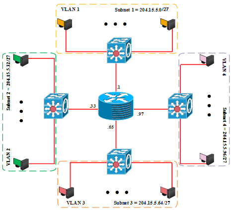
Figure 5. IP Subnet Address based VLAN Membership.
Table 4. VLAN Membership Table with IP Subnet Address and VLAN Mapping.
| IP Subnet | Host Address Range | VLAN |
| 204.15.5.0 | 1-30 | 1 |
| 204.15.5.32 | 33-62 | 2 |
| 204.15.5.64 | 65-94 | 3 |
| 204.15.5.96 | 97-126 | 4 |
In this approach, the VLAN membership is based on the Layer 3 header. The network IP subnet address can be used to classify VLAN membership [4], [6]. Furthermore, it is noteworthy that, the IP addresses are used only for the mapping and have nothing to do with the network routing. Also, the workstations can move without reconfiguring the network addresses. However, this approach requires more time because it takes relatively longer time to forward packets using Layer 3 information than using MAC addresses [4]. A subnet address based VLAN membership is depicted in Figure 5 and the mapping is shown in Table 4.
3.5. Higher Layer VLAN
The higher Layer VLAN membership is based on the higher Layer applications, services and the combination of both [4], [12]. In this approach, file transfer protocol (FTP) applications can be implemented on one VLAN while telnet applications are employed on another VLAN. The Layer 1 and Layer 2 VLAN memberships are defined by the 802.1Q standard while other VLAN membership approaches are proprietary [4]. Furthermore, there is need for connection of the workstations to their respective VLANs and the connection of different VLANs’ traffic between the network devices.
4. VLAN Connection
The frame in a switched environment are handled according to the type of links in which they are passing through which are categorized as access and trunk links [12]. These are links that connect workstations to the VLANs and multiple VLAN traffic between the network devices. An access link is normally assigned to a specific VLAN while trunk link is associated to all VLANs.
4.1. Access Link
An access link belongs to only one VLAN and carries the associated VLAN traffic. The access link is also known as the native VLAN of the port and it is use to connect end devices [12]. Devices that connect to the access link are unaware of the VLAN membership as they assume that they are in a broadcast domain. Due to the fact that the access link connection understands only standard Ethernet frames, the switch removes any VLAN information from the frame before sending it to the access link device. Furthermore, access link devices in a VLAN cannot communicate with devices in another VLAN [12].
4.2. Trunk Link
A trunk link can carry multiple VLANs’ traffic and it is a point-point link that is used to connect switches to other switches or to routers or to servers. Unlike the access link that carries a VLAN traffic, many VLAN traffic can be transported between switches with a single physical trunk link [12]. Figure 6 shows how the access and the trunk links can be employed in a network. The hosts are connected to the access links to communicate with the switch and they can only access a VLAN to which the access links belong and for inter-VLAN communication, a router is required [1]. Moreover, the switch can communicate with all VLANS because they are connected by a trunk link. According to [1], for the number of nodes ![]() in VLAN
in VLAN![]() , and for the traffic from node
, and for the traffic from node ![]() to
to ![]() in the traffic matrix given by
in the traffic matrix given by![]() , the total traffic of
, the total traffic of ![]() is expressed as
is expressed as
![]() (1)
(1)
Also, intra-VLAN traffic ![]() for VLAN
for VLAN![]() is expressed as
is expressed as
![]() (2)
(2)
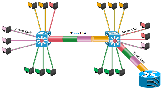
Figure 6. Access and Trunk Links.
5. VLAN Identification
The trunk links are used to carry multiple VLANs’ traffic between devices over the same link. However, the switch needs additional information to know the VLAN that the traffic belongs to in order to forward the frame to those ports that belong to the specified VLAN, instead of forwarding it to all output ports of the switch as can be observed in a normal situation. The switch can determine the required VLAN that the traffic belongs to with the help of additional information known as VLAN identifier. The VLAN identifier is a tag that encapsulates the data. The frame with a tag header is known as tagged frame [13]. Tagged frame conveys VLAN information across the network and this identification is what switches use to classify the VLAN that the frame belongs to [12].
There are two most common types of VLAN encapsulation that can be employed to convey data from multiple VLANs over the trunk links. The first one is the Cisco proprietary trunking mechanism known as Inter-Switch Link (ISL) which is a frame encapsulation method that adds a header to identify the VLAN [11]. Also, the most widely used one is an IEEE industry-standard trunking protocol named IEEE 802.1Q which is a frame-tagging mechanism in which a VLAN identifier is added to the frame by inserting a tag at Layer 2 [13], [15], [16]. Being an open standard, IEEE 802.1Q is normally employ in a network in which switches and other network devices are from different vendors [12]. The 802.1Q operates by using an internal tagging mechanism to insert a 4-byte tag field into the original Ethernet frame and then re-computes the frame check sequence (FCS) before the device send the frame over the trunk link [8]. The tag is removed at the receiving end where the frame is forwarded to the assigned VLAN. The 802.1Q inserts the tag field between the Source Address (SA) and Type/Length fields of the original Ethernet frame. This modification necessitates the need for the trunking device to re-compute the FCS on the tagged frame [8]. A typical IEEE 802.1Q Frame is depicted in Figure 7.
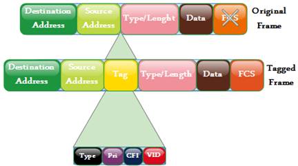
Figure 7. IEEE 802.1Q Frame.
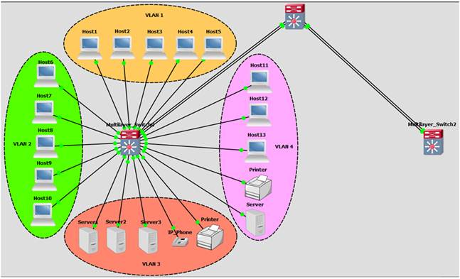
Figure 8. Experimental Network Architecture.
6. Experimental Implementation Results and Analysis
This section contains two sub-section in which the first sub-section presents practical application of VLAN for logical network segmentation based on job types. Moreover, the second sub-section shows the implementation of an IEEE 802.1Q trunking protocol frame-tagging mechanism which enables multiple VLANs’ traffic between devices over the trunk link. The network is made up of three multilayer switches with four VLAN membership. For simplicity, only the analysis for the end devices and VLANs in the first multilayer switch is presented. The network architecture employed is simulated using Cisco Packet Tracer, a graphical network simulator. The system topology is shown in Figure 8.
6.1. Experiment 1: VLAN Network Segmentation
This sub-section demonstrates how VLAN can be used to logically segment a network based on the job types. The workstations are connected to the switch as shown in Figure 8. The aim of this demonstration is to create different VLANs according to the job types in Table 5 and to assign port membership to the respective VLANs. To demonstrate this, the default state of the switch is checked with show VLAN command to confirm that all ports are initially in the native VLAN as shown in Figure 9. Then, the switch is configured for the required VLANs as shown in Figure 10. Furthermore, the ports are then allocated to each VLAN according to Table 5 as shown in Figure 11. The final VLAN status of the switch is depicted in Figure 12.
Table 5. VLANs and the Job Types.
| VLAN | Name | Port |
| 1 | - | FastEthernet 0/1 to FastEthernet 0/5 |
| 2 | Engineering | FastEthernet 0/6 to FastEthernet 0/10 |
| 3 | Marketing | FastEthernet 0/11 to FastEthernet 0/15 |
| 4 | Accounting | FastEthernet 0/16 to FastEthernet 0/20 |
| 5 | Unused | FastEthernet0/21 to FastEthernet0/24 GigabitEthernet 0/1 and GigabitEthernet 0/2 |
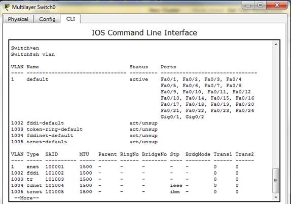
Figure 9. Default State of the Switch.
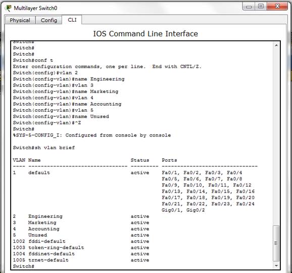
Figure 10. Switch Configuration for the required VLANs.
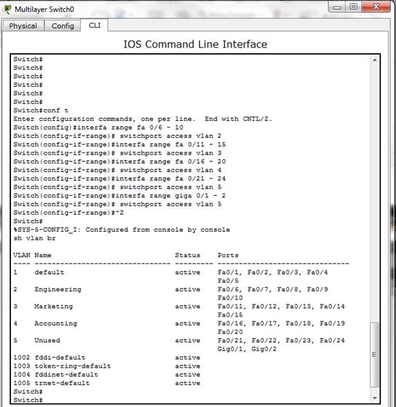
Figure 11. Ports Allocation to the VLAN.
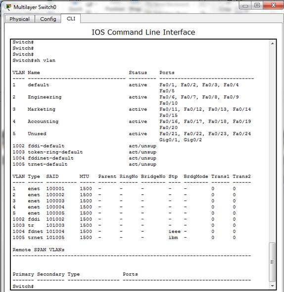
Figure 12. Final VLAN Status of the Switch.
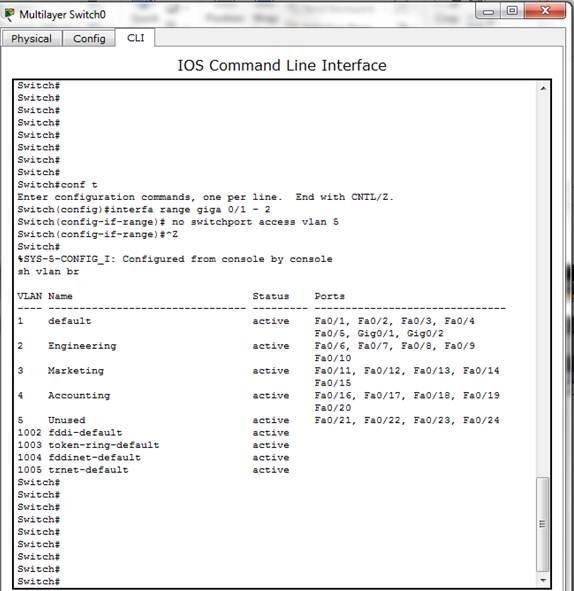
Figure 13. Gigabit Interface removal from Unused VLAN.
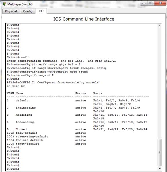
Figure 14. Trunking of Gigabit Interfaces.
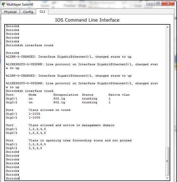
Figure 15. Status of the Gigabit Interfaces.
6.2. Experiment 2: IEEE 802.1Q Trunking
This sub-section shows the implementation of an IEEE 802.1Q trunking for multiple VLANs’ traffic between devices over the trunk link. To demonstrate this, the interface GigabitEthernet 0/1 and 0/2 are moved out of the unused VLAN created in the previous experiment to the native VLAN. The result is shown in Figure 13. Then, the encapsulation is implemented with the IEEE 802.1Q to enable multiple VLANs’ traffic between devices over the trunk link and the switchport mode of both gigabit interfaces are configure as trunk as shown in Figure 14. Also, the show trunk command is used to confirm the current status of both gigabit interfaces and the result presented in Figure 15 shows that both interfaces are in native VLAN and are using IEEE 802.1Q trunking.
7. Conclusions
The traditional Local Area Network (LAN) has the ability to significantly reduce an organization operational costs because of its efficient support for multipoint-to-multipoint (MP2MP) services instead of relying on separate technologies. However, network segregation with the LAN is challenging when different levels of security and access are required by different network groups in an organization. Employment of Virtual Local Area Network (VLAN) for the network segregation has been observed as a viable solution because, it can effectively contain the broadcast traffic and prevent bandwidth wastage which is a drawback inherent to the traditional switched networks in order to enhance the system performance. Therefore, VLAN addresses scalability, flexibility, security, and network management issues that are associated with the traditional LAN. This paper presents practical application of network virtualization by the implementation of the VLAN for logical network segmentation based on job types. In addition, the implementation of an IEEE 802.1Q trunking protocol frame-tagging mechanism is demonstrated.
References
- A. Hameed and A.N. Mian, "Finding efficient VLAN topology for better broadcast containment," 2012 International Conference on the Network of the Future, pp.1-6.
- Batayneh, M.; Schupke, D.; Hoffmann, M.; Kirstaedter, A.; Mukherjee, B., "Reliable Multi-Bit-Rate VPN Provisioning for Multipoint Carrier-Grade Ethernet Services Over Mixed-Line-Rate WDM Optical Networks," IEEE/OSA Journal of Optical Communications and Networking, vol.3, no.1, pp.66,76, 2011.
- M. Huynh, S. Goose, P. Mohapatra, R. Liao, "RRR: Rapid Ring Recovery Submillisecond Decentralized Recovery for Ethernet Ring," IEEE Transactions on Computers, vol.60, no.11, pp.1561-1570, 2011.
- U. Sehgal, Ms. Anu and Ms. Prity, "Virtual Local Area Networks Technologies Implementation and Developments in last few years classified by Port, MAC Address and LAN Based Protocol," International Journal of Advances in Engineering Research, vol. 4, Issue 4, 2012.
- S. Ziyu, J. Xin, J. Wenjie, C. Minghua and C. Mung, "Intra-data-center traffic engineering with ensemble routing," 2013 Proceedings IEEE INFOCOM, pp.2148-2156.
- Z. Syed, S. Joshi, R. R. Vikram and J. Kuriakose, "A novel approach to naval architecture using 1G VLAN with RSTP," 2014 Eleventh International Conference on Wireless and Optical Communications Networks, pp.1-5.
- Y. Minlan, J. Rexford, S. Xin, R. Sanjay and N. Feamster, "A survey of virtual LAN usage in campus networks," IEEE Communications Magazine, vol.49, no.7, pp.98-103, 2011.
- Cisco Systems, Cisco IOS Switching Services Configuration Guide, Release 12.2
- I. A. Alimi, A. O. Mufutau, T. D. Ebinowen, "Cost-Effective and Resilient Large-Sized Campus Network Design," American Journal of Information Science and Computer Engineering, vol. 1, no. 1, pp. 21-32, 2015.
- L. Fuliang, Y. Jiahai, A. Changqing, W. Jianping, W. Siyang and J. Ning, "CSS-VM: A centralized and semi-automatic system for VLAN management," 2013 IFIP/IEEE International Symposium on Integrated Network Management, pp.623-629.
- S. McQuerry, CCNA Self-Study: Interconnecting Cisco Network Devices (ICND) 640-811, 640-801, 2nd Edition, Cisco Press, 2004.
- T. Lammle and A. Barkl, CCDA: Cisco Certified Design Associate Study Guide: Exam 640-861, 2nd Edition, John Wiley & Sons, 2006
- Cisco Networking Academy, Routing and Switching Essentials Companion Guide, 1st Edition, Cisco Press, 2014.
- S. Li, S. Sharma, D. Katramatos and Y. Dantong, "Optimizing circuit allocation for bandwidth reservations in dynamic virtual circuit networks," 2015 International Conference on Computing, Networking and Communications, pp.817-823.
- T. Hirotsu, K. Fukuda, H. Abe, S. Kurihara, O. Akashi and T. Sugawara, "Dynamic and distributed routing control for virtualized local area networks," 2010 IEEE Conference on Local Computer Networks pp.212-215.
- X. Ren, Z. Jun-feng and Y. Yu, "Research of access control strategy in EOC system based on VLAN," 2012 International Symposium on Information Technology in Medicine and Education, vol.2, pp.893-896.
Biography
|
|
|
|


