
International Journal of Automation, Control and Intelligent Systems, Vol. 1, No. 3, September 2015 Publish Date: Aug. 13, 2015 Pages: 85-91
Direct Fuzzy Control of One Axis Manipulator
Ayman A. Aly*
Mechanical Engineering Dept., College of Engineering, Taif University, Taif, Saudi Arabia
Abstract
This paper starts with a section about one DOF electrohydraulic manipulator modelling. After that, research on fuzzy control, theory and application, is surveyed to provide a brief background for the research described in the study. The structure of FLC is presented in details, among which only the conventional FLC is studied thoroughly in this work. Furthermore, the parameters of the controllers were optimized using MATLAB and better results for the time responses were obtained. Finally, the experimental results demonstrate that the proposed controller can work probably.
Keywords
Fuzzy Control, Dynamic Model, Robotic, Manipulator Arm
Received: July 4, 2015
Accepted: July 29, 2015
Published online: August 13, 2015
@ 2015 The Authors. Published by American Institute of Science. This Open Access article is under the CC BY-NC license. http://creativecommons.org/licenses/by-nc/4.0/
Contents
1. Introduction 2. System Description 2.1. Some Nonlinearities of the Model 2.2. Nonlinear Flow Gain Characteristic 3. Design of the Fuzzy Controller 3.1. Scaling Factors 3.2. Fuzzification 3.3. Decision Marking 3.4. Fuzzy Inference 3.5. Defuzzification 3.6. Design Procedure of FLC 4. Simulation and Practical Results 5. Conclusion
1. Introduction
The first step in control system design is to obtain the mathematical model, which, describe the dynamics of the plant to be controlled. More accurate dynamic model of the plant led to better control system performance. However in some cases in order to simplify the model, some assumptions must be made including linearization of some components.
Traditionally, system identification relied on a priori knowledge such that mechanistic models, which completely describe the system can be constructed, empirical data is then used to validate these identified models, [1-2].
Fuzzy logic has rapidly become one of the most successful of today's technologies for developing sophisticated control systems. The reason for which is very simple. Fuzzy logic addresses such applications perfectly as it resembles human decision making with an ability to generate precise solutions from certain or approximate information. It fills an important gap in engineering design methods left vacant by purely mathematical approaches (e.g. linear control design), and purely logic-based approaches (e.g. expert systems) in system design.
While other approaches require accurate equations to model real-world behaviors, fuzzy design can accommodate the ambiguities of real-world human language and logic. It provides both an intuitive method for describing systems in human terms and automates the conversion of those system specifications into effective models.
The first applications of fuzzy theory were primary industrial, such as process control for cement kilns. However, as the technology was further embraced, fuzzy logic was used in more useful applications. In 1987, the first fuzzy logic-controlled subway was opened in Sendai in northern Japan. Here, fuzzy-logic controllers make subway journeys more comfortable with smooth braking and acceleration. Best of all, all the driver has to do is push the start button! Fuzzy logic was also put to work in elevators to reduce waiting time. Since then, the applications of Fuzzy Logic technology have virtually exploded, affecting things we use every day, [3-5].
2. System Description
The experimental layout of the electro-hydraulic position control system is shown in Figure 1. The control signal is sent from the computer and is put into the servo valve through the D/A converter. The oil flow can be regulated through the valve. The pressure difference between the cylinder chambers is built up and then the position of the cylinder can be under control. The position of the cylinder is measured by a pulse scale, which output is sent to the computer as a feedback signal.
The convenient form of the equation of the servo valve is, [2-5]:
![]() (1)
(1)
where the saturation of the servo valve amplifier is considered,
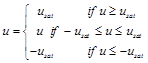
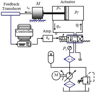
Figure 1. Schematic diagram of the electro-hydraulic system Cylinder position control system.
The equations of the servo-valve flow to and from the actuator (assuming symmetric valve port, zero lap design and zero return pressure) are as follows,
For xv ³ 0
![]() ,
,
![]() (2)
(2)
For xv £ 0
![]() ,
,
![]() (3)
(3)
The flow equations of the actuator are given by:
![]() ,
, ![]() , (4)
, (4)
where ![]() and
and ![]()
It is assumed that the loading point may be treated as a mass-damper system. The equation for the force developed by the actuator on the loading point can be written as
![]() (5)
(5)
2.1. Some Nonlinearities of the Model
The servo-valve possesses several nonlinearities. They are principally, the change in flow gain near null, the nonlinear nature of the pressure-flow relationship, torque-motor hysterics, flow saturation and valve spool friction. It will be assumed that the electronic control system is designed to work below the signal saturation limits therefore the saturation in this stage can be neglected, [6].
2.2. Nonlinear Flow Gain Characteristic
In Figure 2 the change of flow near null can be attributed to manufacturing tolerances, [6]. If the width of the spool land is smaller than the port in the valve sleeve where the spool is at neutral, the valve is said to be under-lapped. A zero-lapped valve has a spool land identical to the port width. It is also showed that within the under lap region, the under-loped valve may have a flow gain twice that of the zero-lapped case, [7-10]. For an overlapped valve, the theoretical flow in the lapped region should be zero resulting in a dead band. However because of practical limitation, minute radial clearances do occur, resulting in some leakage flow leaving the load ports. This gives the reduced flow gain at null (one half of that of zero-lapped valve).
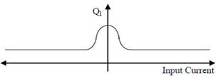
Figure 2. Flow gain characteristic.
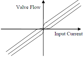
Figure 3. Leakage-Flow Characteristic.
The leakage dominates the performance of the valve at null. A typical curve of leakage flow against valve current under block line condition is shown in Figure 3. The leakage flow curve consists of two parts. One of them is independent of the spool displacement whereas the other is largely dependent on the spool displacement.
The former is mainly due to leakage in the first-stage of the servo valve. This leakage represents a direct power loss but has no other significance. The latter is second-stage null leakage and this affects the damping of the drive at null, [10].
2.2.1. Nonlinear Pressure-Flow Characteristic
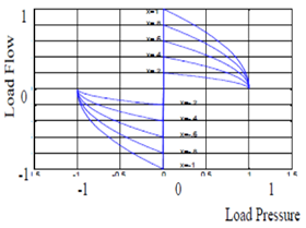
Figure 4. Normalised Valve Pressure-Flow Curves.
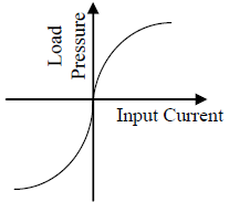
Figure 5. Load Pressure-Input Current.
Typical plots of the normalized valve pressure flow curves ate given in Figure 4. The effect of the null leakage on the load pressure is shown in Figure 5. Therefore care should be taken when interpreting the curves in Figure 5 within the null region.
2.2.2. Friction Nonlinearities
The nonlinear friction characteristics for an electrohydraulic actuator are very complex due to the interaction of such factors as the bearing design, e.g. the type of lubricant used, the contact stiffness and the quality of slide-way alignment. No general model has yet been developed to predict the performance of this non-linearity.
When motion has started the friction level only changes over to the coulomb level when a certain velocity, called the critical velocity, is reached. The velocity range between plus and minus the critical velocity, is termed the stick-slip region. Once outside this region, stick does not re-appear until the velocity falls to zero.
The static and coulomb friction can be summarised as follows
![]() (6)
(6)
where Ff is nonlinear friction force, Fm is coulomb friction, Fst is static friction, Vcr is critical velocity
The first difficult problem encountered in controller tuning is to define what is "good" control, and this unfortunately differs from one to another. The most common practise employed is to adjust the controller to meet the following main performance criteria:
1. Accuracy
2. Speed of response
3. Robustness
The controller parameters are to be selected to minimise the error between the controlled variable and the set point. With the advent of digital computers, various methods of optimisation may be applied to choose the controller constants to reach the optimal performance.
PID controllers are widely used in industry due to their simple structure for many systems. 90% of the control loops in industrial control are PID controllers, [11-13].
3. Design of the Fuzzy Controller
Discretization / Normalization of universe of discourse:
Usually the measured input data is transformed into a normalized universe of discourse (usually [-L]) using the mapping function:
![]() (7)
(7)
where Gxi is the I-th input scaling factor. The mapping function F may be linear or nonlinear.
Sometimes the universe of discourse is discretized (quantified) into certain number of levels, for which the fuzzy sets are defined discretely. For this case a look up table based on the discrete universes, which defines the output of the controller for all possible combinations of the input signals can be implemented by off-line processing of the fuzzy algorithm in order to shorten the running time of the controller.
The choice of the number of quantization level has an essential influence on how fine a control can be obtained.
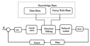
Figure 6. Configuration of FLC.
3.1. Scaling Factors
They are the factors by which the inputs to the control system are multiplied to make lie in the range of the universe of discourse of these fuzzy variables. They lay an important role in the system response because they are similar to the parameters of the PD controller except that the output is limited by a certain value. If the range of discourse normalized to the range of [-L,L] then the scaling factors are determined from
![]() (8)
(8)
These factors require the knowledge of maximum value of E and CE which is not available all time The Umax is easily determined from the maximum available power. Changing these paramours change the performance evidently and there are some guide lines the effect of varying these parameters:
1. If Ge is low this leads to
• Poor response
• Large steady state error
• Local self-Oscillation
2. If Ge is high this increases overshoot.
3. If Gce is increased then
• Tr increases
• Steady state error increased.
• PO% decreases
4. Increasing Gu decreases the rise time Tr
3.2. Fuzzification
It is the process by which the crisp values converted into fuzzy sets in a certain functions are considered a part of this process.
The membership functions (MF) may take one of the forms as shown in Figure 7
The most commonly used functions are trapezoidal and triangular functions (special case of the trapezoidal functions). As the number of membership functions associated with fuzzy variable increases the fuzzification will be smoother which the required rules and memory required to save this information are increased. Also as these functions are overlapped the smoothness increases but no methods were found to determine the degree of overlapping.
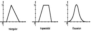
Figure 7. Three Membership Function Shapes.
3.3. Decision Marking
It is the heart of the FLC, having the capability of simulating human decision making on fuzzy concepts, inferring fuzzy control actions employing fuzzy implication, and the rules of inference in fuzzy logic. Basically, decision-making logic performs the function of processing and evaluating fuzzy control rules. This part makes two tasks generating rules and inferring the output from these rules due to the system outputs.
Rules:
It is the most important part of any FLS. It linguistically defines the control policy of the controller. Fuzzy control rules are usually in the form of conditional statements:
If < (antecedent)> Then< (consequent)> (9)
These rules are easy to implement by fuzzy conditional statements in fuzzy logic.
There are many studies to generate these rules. In general, there are four main methods for rule generation which are:
Fuzzy control is the first practical application of expert systems which in its nature suitable for describing linguistically the expert’s thinking which is essentially fuzzy in its nature. Then, if the process under control works well by an operator then it is very useful to make an interview with this operator and get the know-how from him and express this in terms of fuzzy implications. The disadvantages of this method of design is drawn from the fact that, firstly, the process is complex, the engineer’s sense finds difficulty, and secondly, when the process is complex, the engineer’s sense finds difficulty to write down the control rules for this process. Then this method is essentially heuristic. So, it is very difficult to give a general design procedure. This method is used to generate the rules for an equivalent PD controller derived from the engineer’s sense.
First let us define the error (E) and the change in error (CE) and also the control action to the system U having 7 membership function defined on the normalized interval [1,1] and having the following fuzzy sets as shown in Figure 8 NL is Negative Big, NM is Negative Medium, NS is Negative Small, ZO is Zero, PS is Positive Small, PM is Positive Medium, PL is Positive Big.
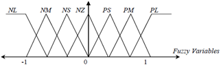
Figure 8. Definition of Membership Function For Fuzzy Variables (E, CE and U).
By observing the response of the system, we can generate the rules of a controller capable of improving the system performance as shown in Table 1
Table 1. Classical Fuzzy Controller Rule Matrix.
| CE | ||||||||
| E | U | NL | NM | NS | ZO | PS | PM | PL |
| NL | NB | NB | NB | NM | NM | NS | ZO | |
| NM | NB | NB | NB | NM | NS | ZO | PS | |
| NS | NB | NM | NM | NS | ZO | PS | PM | |
| ZO | NB | NS | NS | ZO | PS | PM | PB | |
| PS | NM | NS | ZO | PS | PM | PB | PB | |
| PM | NS | ZO | PS | PM | PB | PB | PB | |
| PL | ZO | PS | PM | PM | PB | PB | PB | |
3.4. Fuzzy Inference
By inference we mean obtaining the controller output fuzzy set from the controller input and the control rules by compositional rule of inference.
If two main operators defined before, are the max.-min (Zadeh) and the max.-product.
The fuzzy reasoning algorithm (implication and inference) for a set of control rules can be performed in 2 ways, either by rule matrices or rule by rule.
In the first method, which is suitable for discrete universes, the rule matrix for each rule Ri is obtained throughout fuzzy implication, then the final control rule for the whole algorithm is obtained using the Union of all the matrices Ri. Finally the output fuzzy set is obtained by the compositional rule of inference. This method is suitable only for SISO systems that generates 2-D rule matrix. If the input increases this method can be applied. Even for SISO, the dimension of the rule matrix and consequently the memory needed for storing it increases with increasing the quantization levels.
In the second method, rule by rule method, the membership function for each rule and the corresponding output fuzzy set is first obtained using min or product implication operators, then, the final output fuzzy set is obtained using union (max.). This method is more general since it is suitable for both discrete and continuous universes of discourse and can be applied for any number for the inputs and outputs.
Throughout this thesis, the second method is used except that for the SOFLC algorithms in which look-up table is used.
3.5. Defuzzification
It is the process by which the fuzzy output from the decision making part converted to crisp values suitable to the physical.
The output from this method is the centre of area of the shape resulted from intersection of the output membership functions and the intensity of the rule from that related to this membership function that is given by:
![]() (10)
(10)
3.6. Design Procedure of FLC
In the previous section, we give an overview about the structure of the FLC and methods of designing each part. The procedure that designers follow for obtaining FLC is as follows:
i. The no of inputs that have the greatest effect on the system behaviour must be first investigated (like D and CE) for PD controller of (E, CE, and CEE) for systems that are highly unstable or any system states depending on your knowledge about the system. The output variables are also defined.
ii. The membership function associated with each variable are selected depending on your experience and choosing their universe of discourse normalized into suitable region like [-L, L] or a suitable one depending the problem handled. The commonly used membership functions are the trapezoidal and triangular.
iii.Construct the controller algorithm depending on one of the mentioned methods of rule generation or depending on the available data.
iv. Select the method of rule inference that is the method of obtaining the output from the measured input combined with the rule base.
v. The final method is the defuzzification method (e.g., the weighted average method) that is commonly used and gives smooth response. The scaling factors must be determined according to the understanding of the system under control
Finally, it is a trial and error method and requires simulations to get the best choice result and no analytical solution was found but only your experience and sense.
4. Simulation and Practical Results
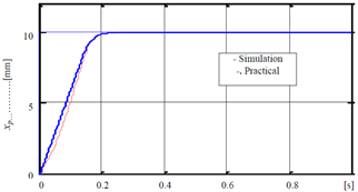
Figure 9. System step response based on fuzzy control.
Table 2. Step input response results.
| Controller | Td | Ts | Tr |
| FuzzyTh | 0.046 sec. | 0.1 sec. | 0.126 sec. |
| FuzzyP | 0.04 sec. | 0.12 sec. | 0.115 sec. |
Th = Theoretical, P = Practical
A software program utilizing C++ language is developed based on Rung Kuta fifth order to perform the difference equation through the PC. The study of the results will be according to the transient response characteristics of the system response. The real time implementation was carried out using the same sampling time (3msec) and the same reference step input. The control algorithm is implemented by a personal computer, based on a 533 MHz Celeron processor.
The simulation and practical results to step reference based on the conventional fuzzy controller are shown in Figure 9. The summary of comparison is shown in Table 2 based on the delay time (Td), the rise time (Tr) and the settling time (Ts ). The cross bonding controller signal is shown in Figure 10.
In Figure 11, the time responses of two tests were carried out with the same reference step input. One is with a spring (7×10⁵ N/m), which was added in the half stroke of the cylinder as a disturbance for the hydraulic system, and the other is without spring.
It is found that the delay time difference was 0.026 sec. and the steady state error was 1.2%.
The control problem of electro hydraulic cylinder is studied in this paper. A fuzzy controller has been given. The main advantage of the fuzzy that is faster than the PID controller. It is found by applying the fuzzy control, which is based on the fuzzy sets theory to improve the system response characteristics but still the fuzzy controller cannot use the maximum velocity of the system. If we increased the controller gain we would get steady state error because the fuzzy controller is a PD variable gain controller (i.e. it has no integral gain to overcome the steady state error.).
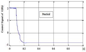
Figure 10. Controller signal for step input based on fuzzy logic.
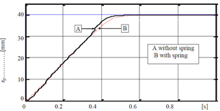
Figure 11. System step response based on Fuzzy control
5. Conclusion
The control problem of a nonlinear system such as the electro hydraulic cylinder is studied in this paper. A fuzzy controller has been implemented.
The main advantage of the proposed fuzzy control:
• The control algorithm is simple
• The algorithm is easy to implement even on small microprocessor systems.
• Through the simulations and experiments using the servo valve controlled cylinder system, the effectiveness and robustness of the fuzzy control was confirmed.
The main disadvantage of the proposed fuzzy control:
• There is a difference between the simulation and the practical work according to the fact that the used model in the simulation is time invariant parameters however the real plant actually is time variant parameters.
References
- Z.-X. Cai, "Intelligent Control", Electronics Industry press, Beijing, China, 1996.
- Ayman A. Aly "Modelling and control of an electro-hydraulic servo motor Applying velocity feedback control strategy", International Mechanical Engineering Conference & Expo (IMEC2004), Kuwait.
- Ayman A. Aly and Aly S. Abo El-Lail, "Self Tuning PI Fuzzy Position Control of A Hydraulic Manipulator" Journal of Engineering Science, JES, Vol. 33, No. 1, pp 199-209, January 2005.
- Khalil A. Khalil, Ayman A. Aly and A. Abo-Ismail, "Tip Position Control of A Single Flexible Arm", International Conference on Mechatronics (ICOM05), Malaysia.
- Ayman A. Aly, "A Non Linear Optimal PID Control of A Hydraulic Crane" Journal of Engineering Science, JES, Vol. 33, No. 1, pp 199-209, Feb. 2007.
- Ayman A. Aly and S. Elnaggar, "Genetic PD Control of a Three-Link Rigid Spatial Manipulator," International Journal on Automatic Control System Engineering, ICGST-ACSE Journal, Vol. 11, No.1, pp 15-22, June 2011, Germany.
- Ayman A. Aly, Aly S. Abo El-Lail, Kamel A. Shoush, Farhan A. Salem," Intelligent PI Fuzzy Control of An Electro-Hydraulic Manipulator," I. J. Intelligent Systems and Applications (IJISA),7,43-49,2012.
- Ayman A. Aly, "Model Reference PID Control of an Electro-hydraulic Drive" I. J. Intelligent Systems and Applications (IJISA), 11, 24-32, 2012.
- Ayman A. Aly, A. A. Alshnnaway,, A. Abo-Ismail, S. Dossokey, "Self-Learning Intelligent Controller of Electro hydraulic Actuator", International Journal of Engineering and Manufacturing (IJEM), Vol.3, No.1, pp.28-37, 2013.
- Ayman A. Aly and Aly S. Abo El-Lail ,"Intelligent PI Fuzzy Control of an Electro-Hydraulic Manipulator", International Journal of Control, Automation And Systems (IJCAS) 3 (2), PP.19-24, 2014.
- Ayman A. Aly, Farhan A. Salem, "Design of Intelligent Position Control for Single Axis Robot Arm", International Journal of Scientific & Engineering Research, Volume 5, Issue 6, pp 790-795, 2014.
- Farhan A. Salem, Ayman A. Aly, "PD Controller Structures: Comparison and Selection for an Electromechanical System", PP.1-12, Vol. 7, No. 2, I. J. Intelligent Systems and Applications (IJISA) January 2015.
- Farhan A. Salem, Ayman A. Aly, Mosleh Al-Harthi and Nadjim Merabtine, "New Control Design Method for First Order and Approximated First Order Systems", International Journal of Control, Automation And Systems (IJCAS) V4 (2), PP 7-17, 2015.


